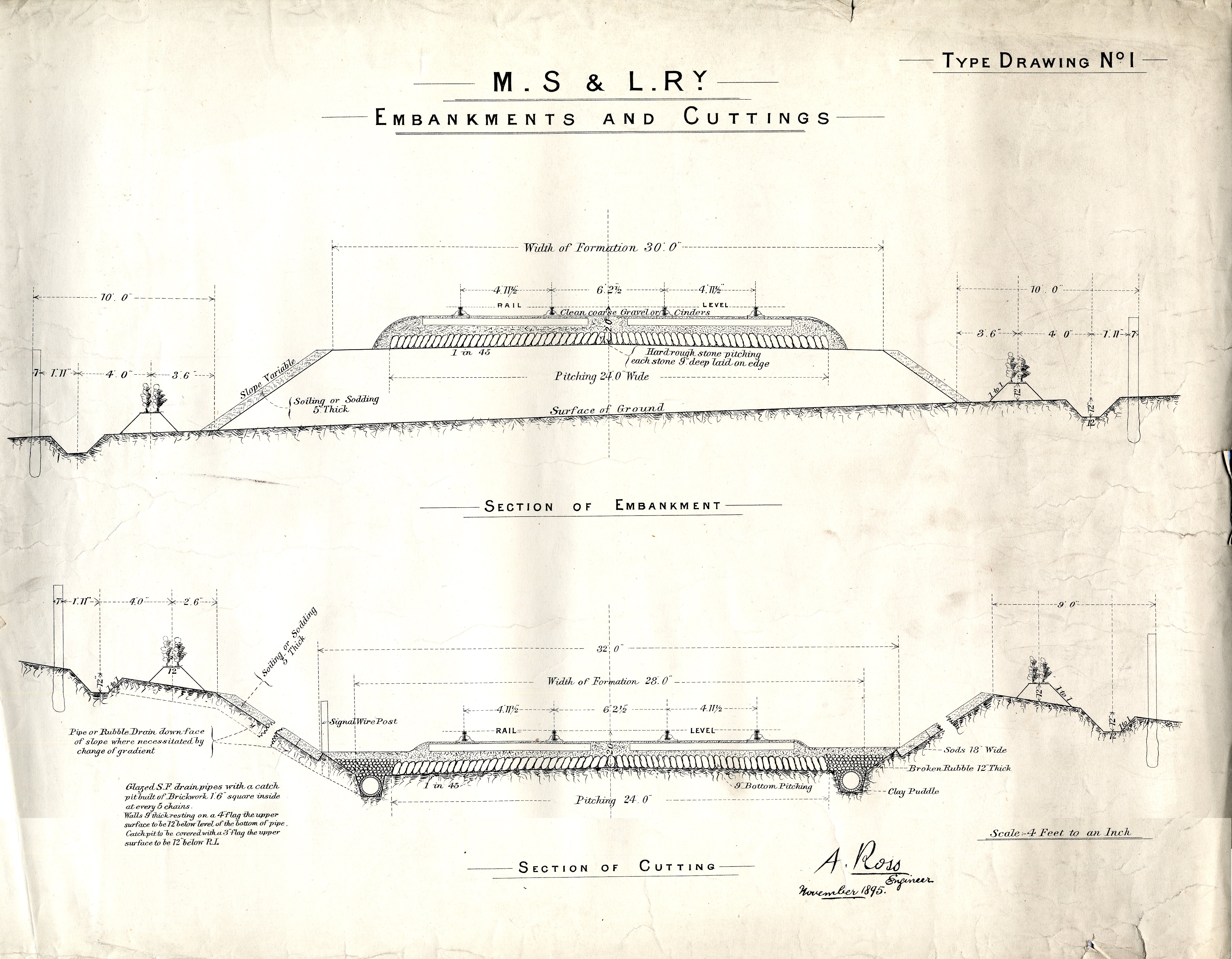
Type Drawing No. 1
Embankments and Cuttings
Section of Embankment
Section of Cutting
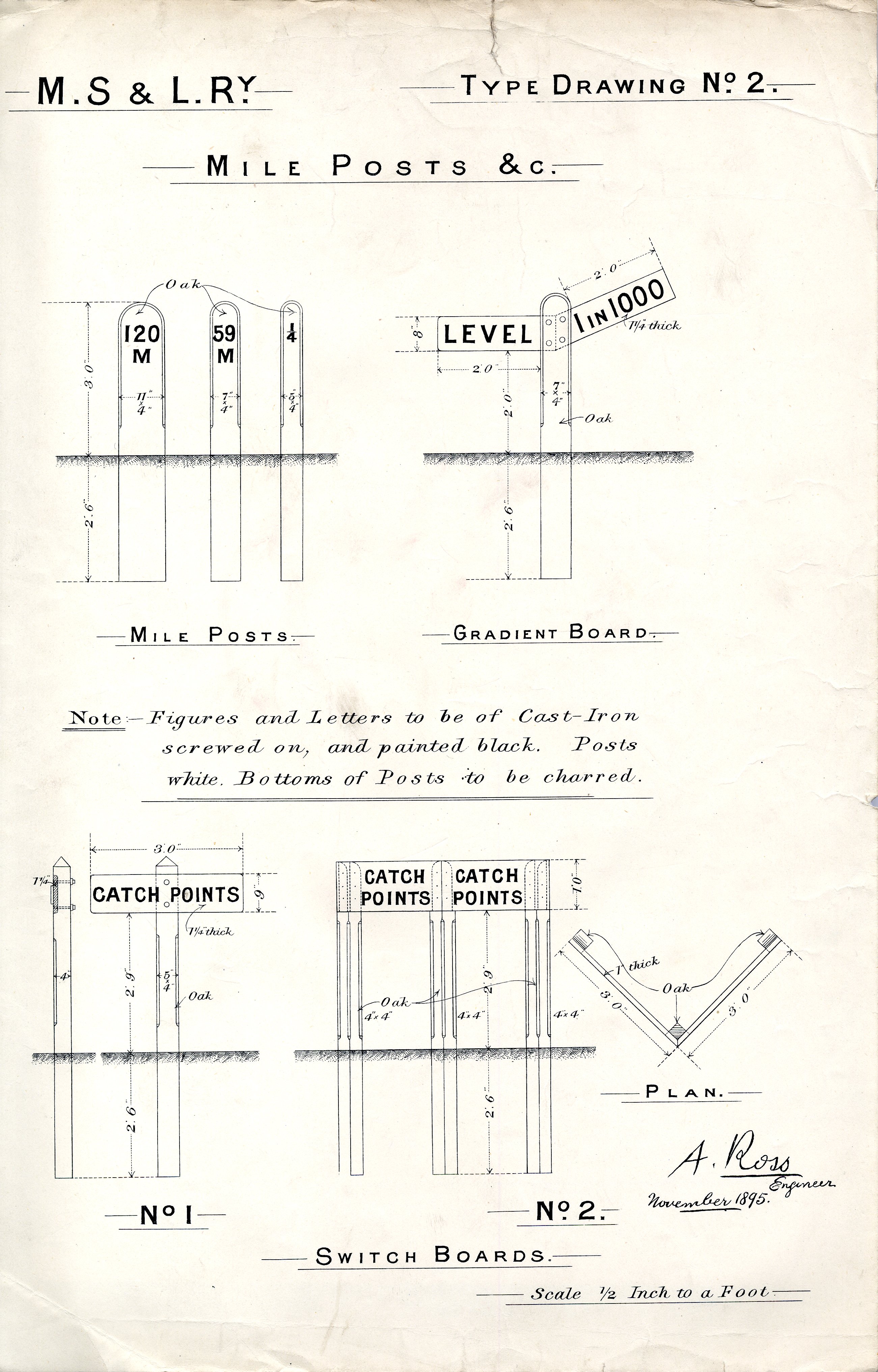
Type Drawing No. 2
Mile Posts &c.
Mile Posts
Gradient Board
Switch Boards
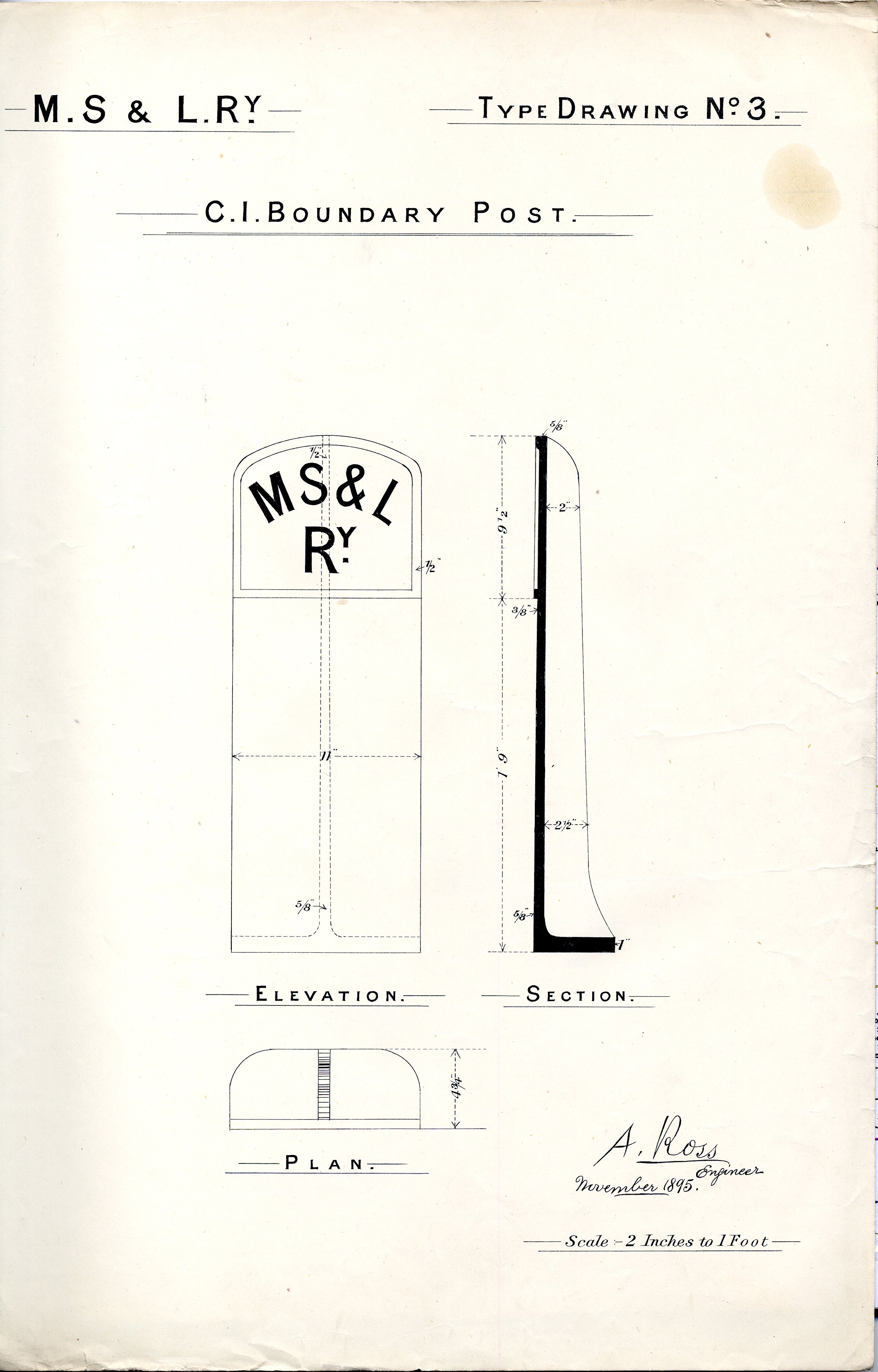
Type Drawing No. 3
C.I. Boundary Post
Elevation
Section
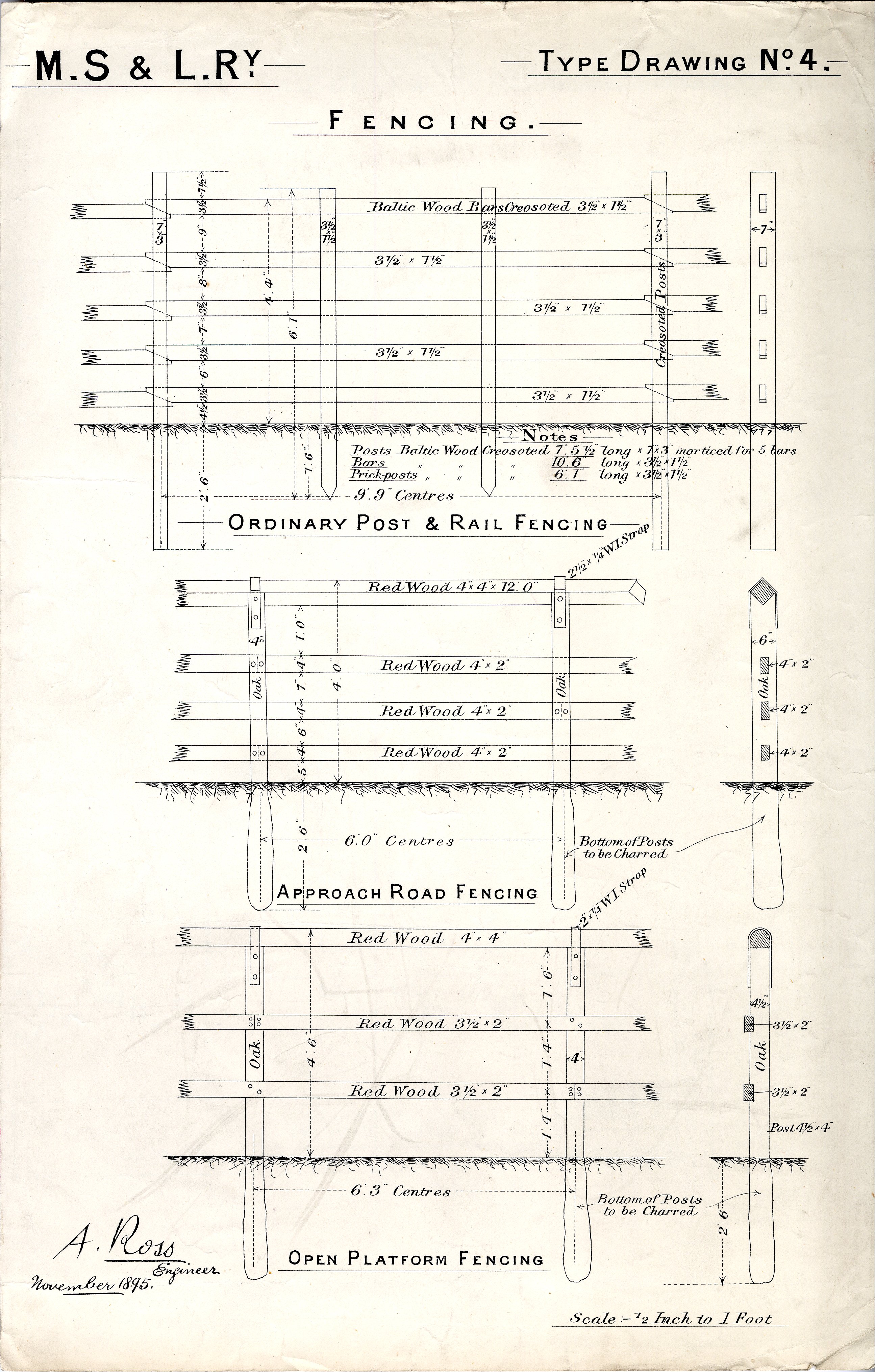
Type Drawing No. 4
Fencing
Ordinary Post & Rail Fencing
Approach Road Fencing
Open Platform Fencing
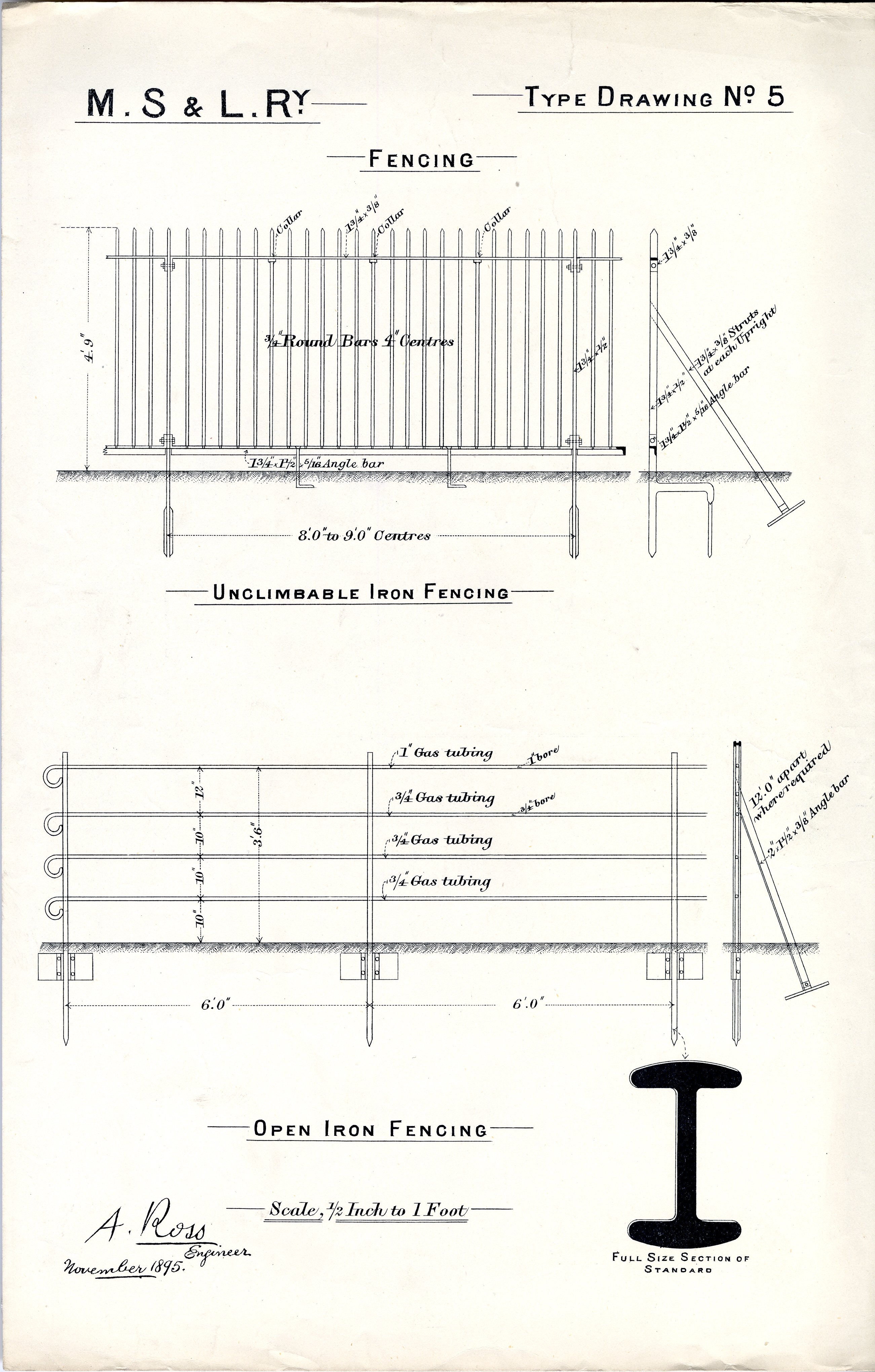
Type Drawing No. 5
Fencing
Unclimbable Iron Fencing
Open Iron Fencing
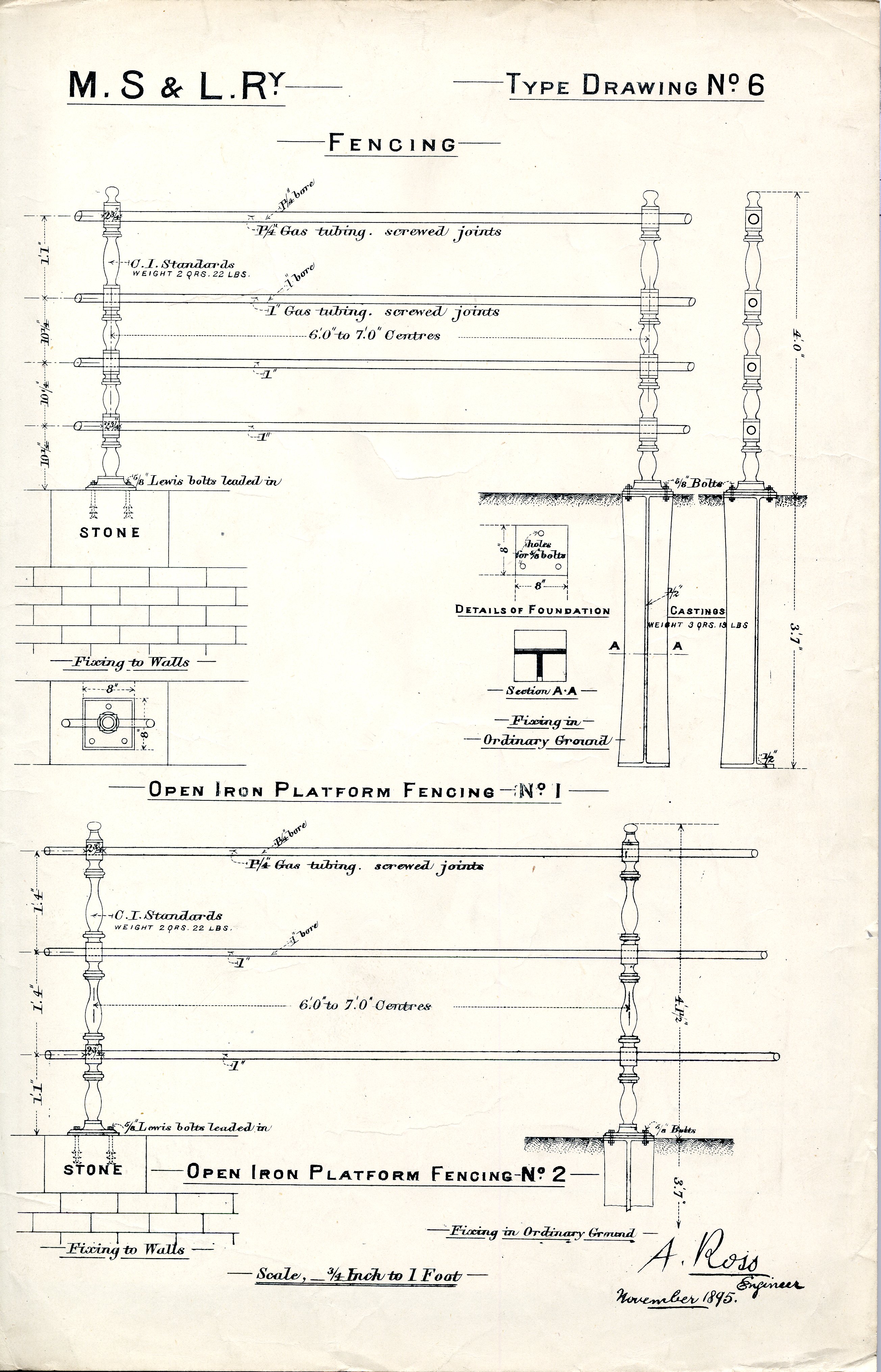
Type Drawing No. 6
Fencing
Open Iron Platform Fencing No. 1
Open Iron Platform Fencing No. 2
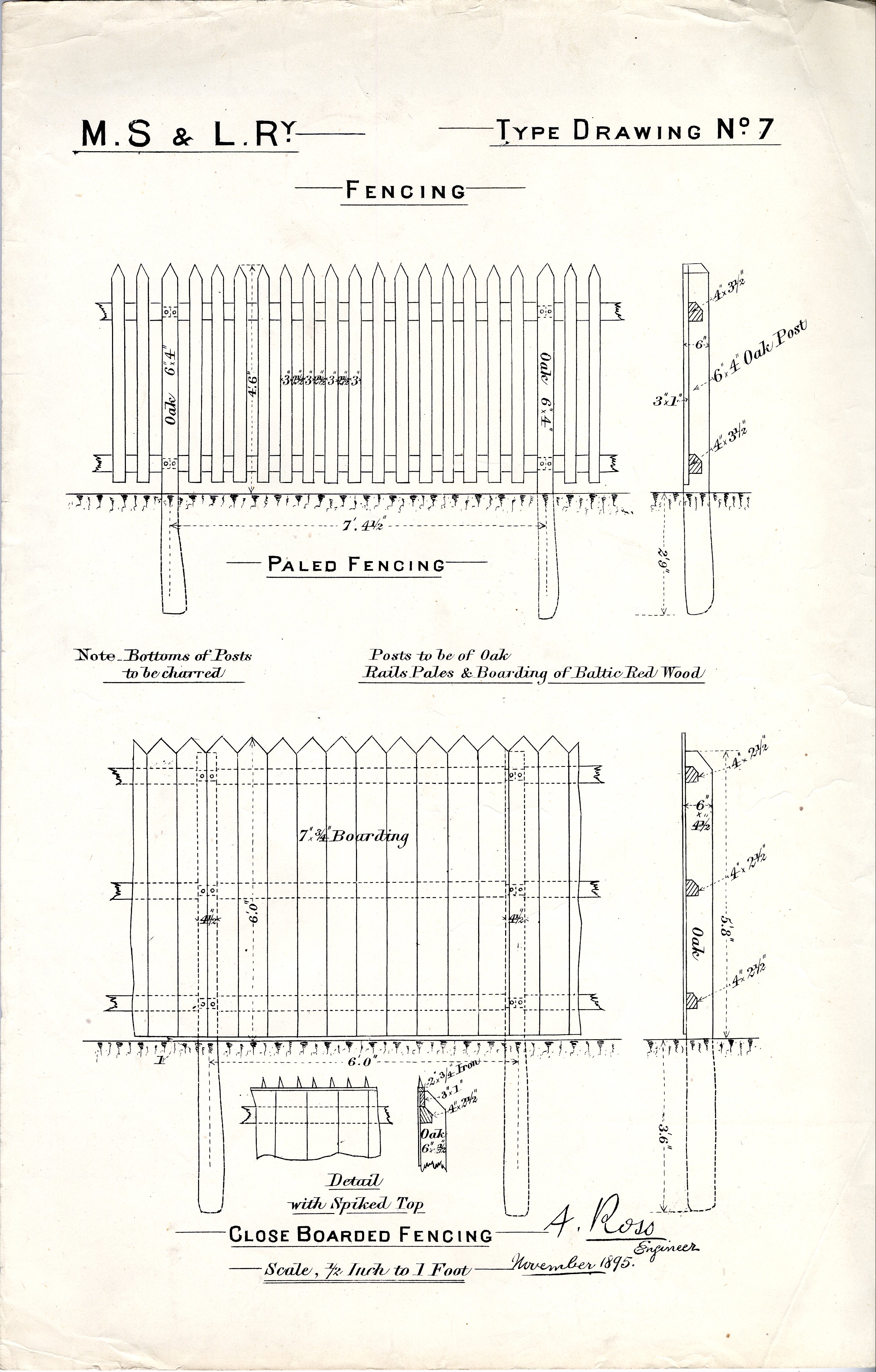
Type Drawing No. 7
Fencing
Paled Fencing
Close Boarded Fencing
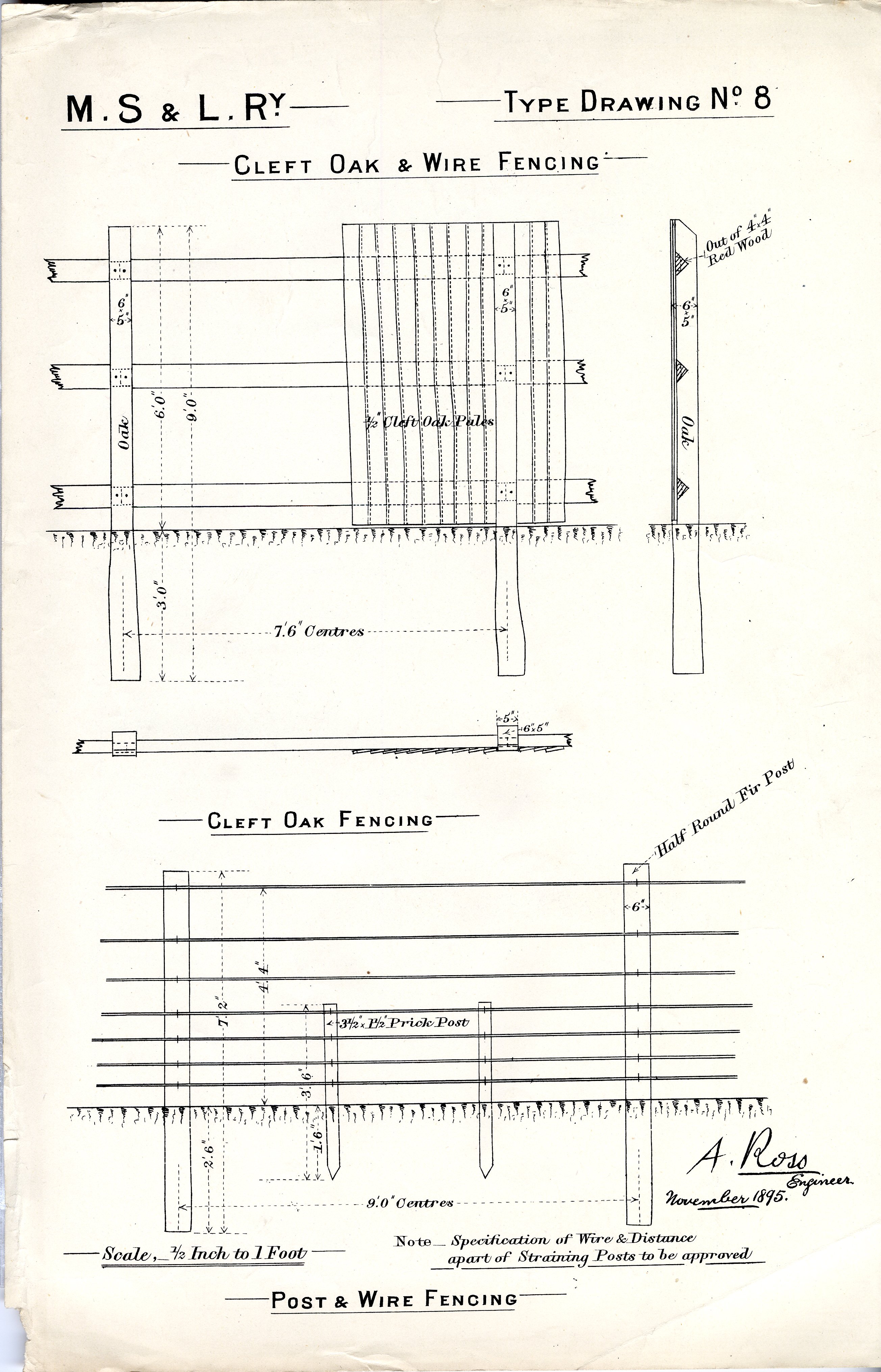
Type Drawing No. 8
Cleft Oak & Wire Fencing
Cleft Oak Fencing
Post & Wire Fencing
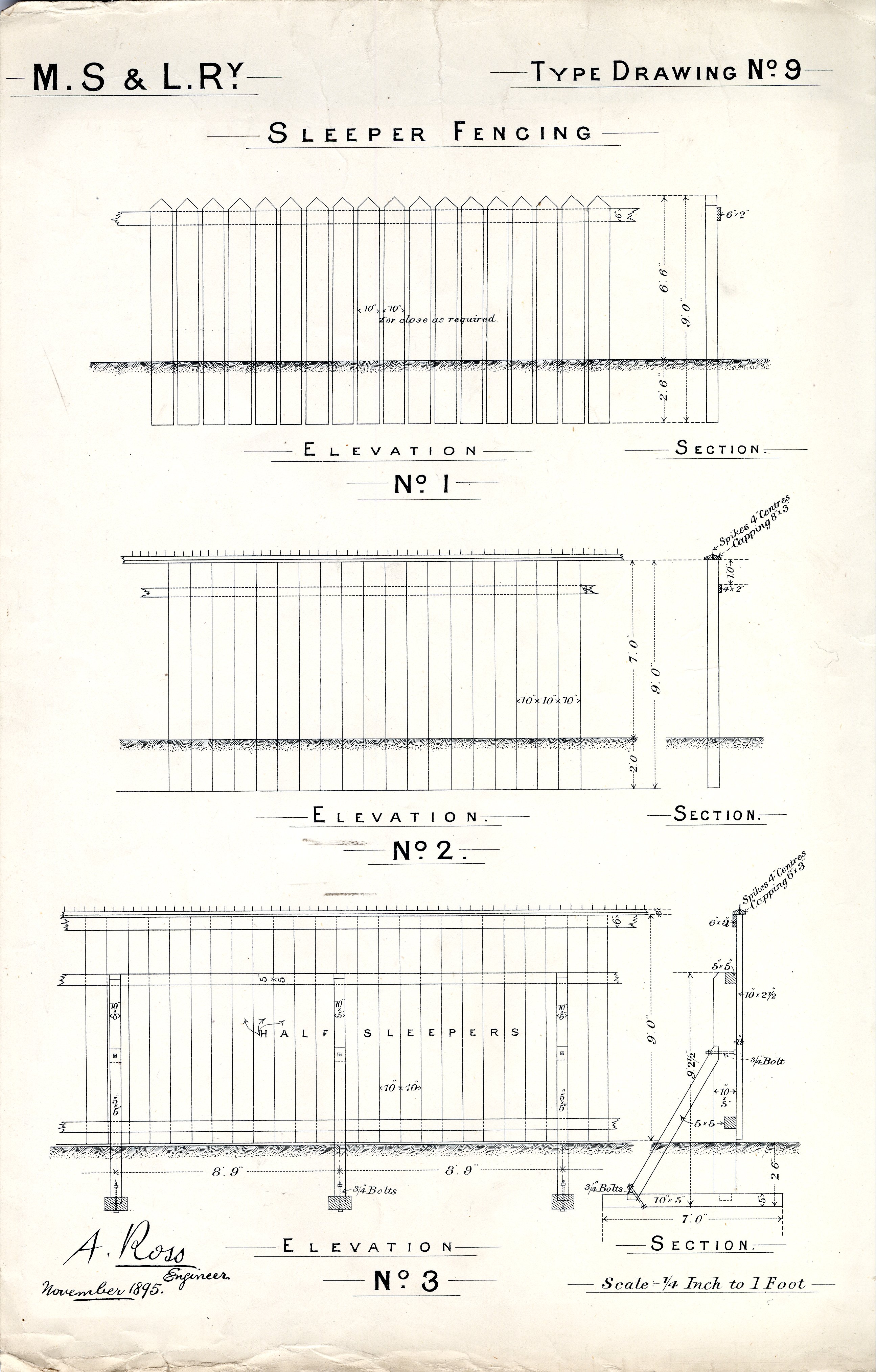
Type Drawing No. 9
Sleeper Fencing
No. 1
No. 2
No. 3
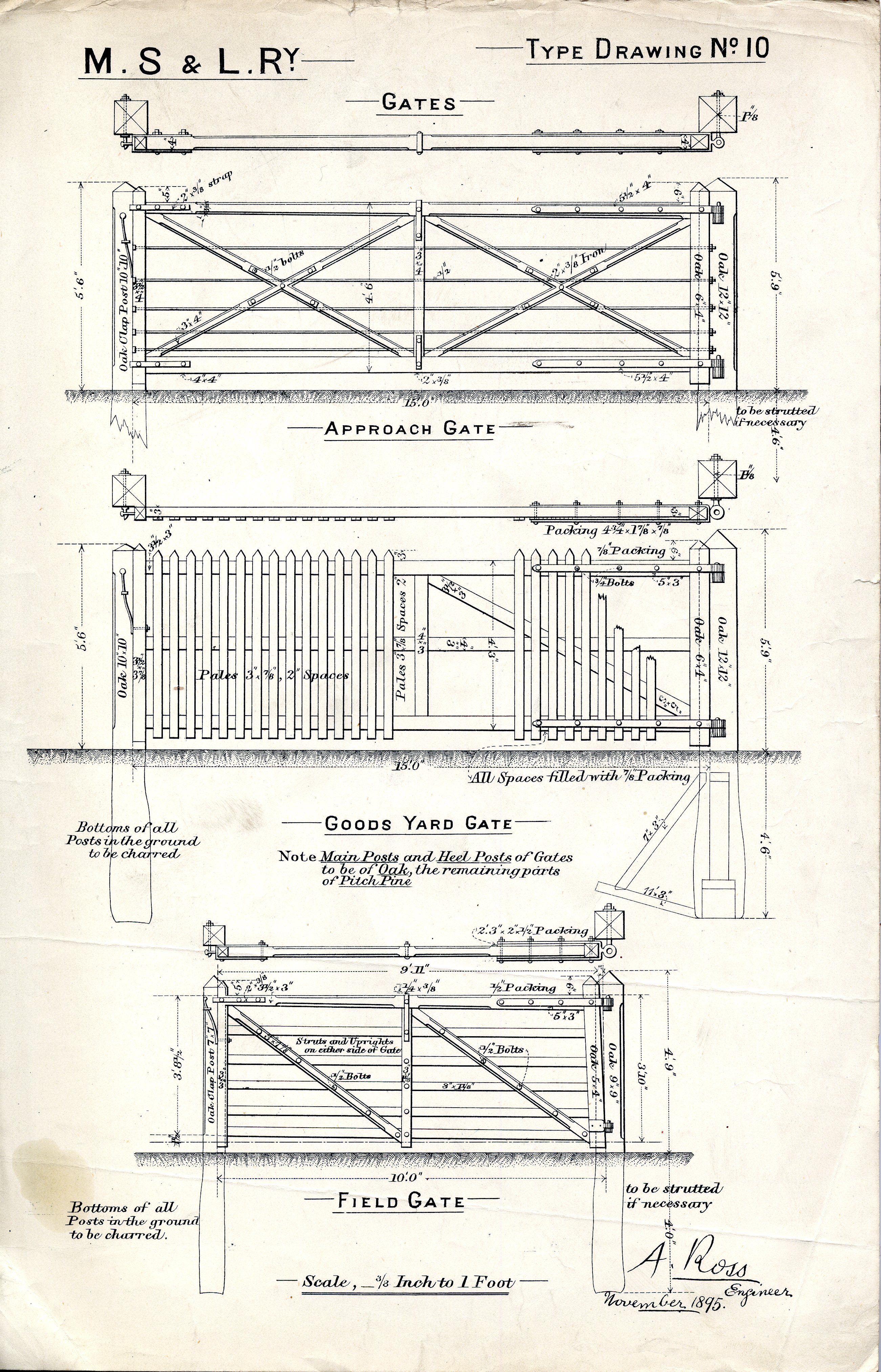
Type Drawing No. 10
Gates
Approach Gate
Goods Yard Gate
Field Gate
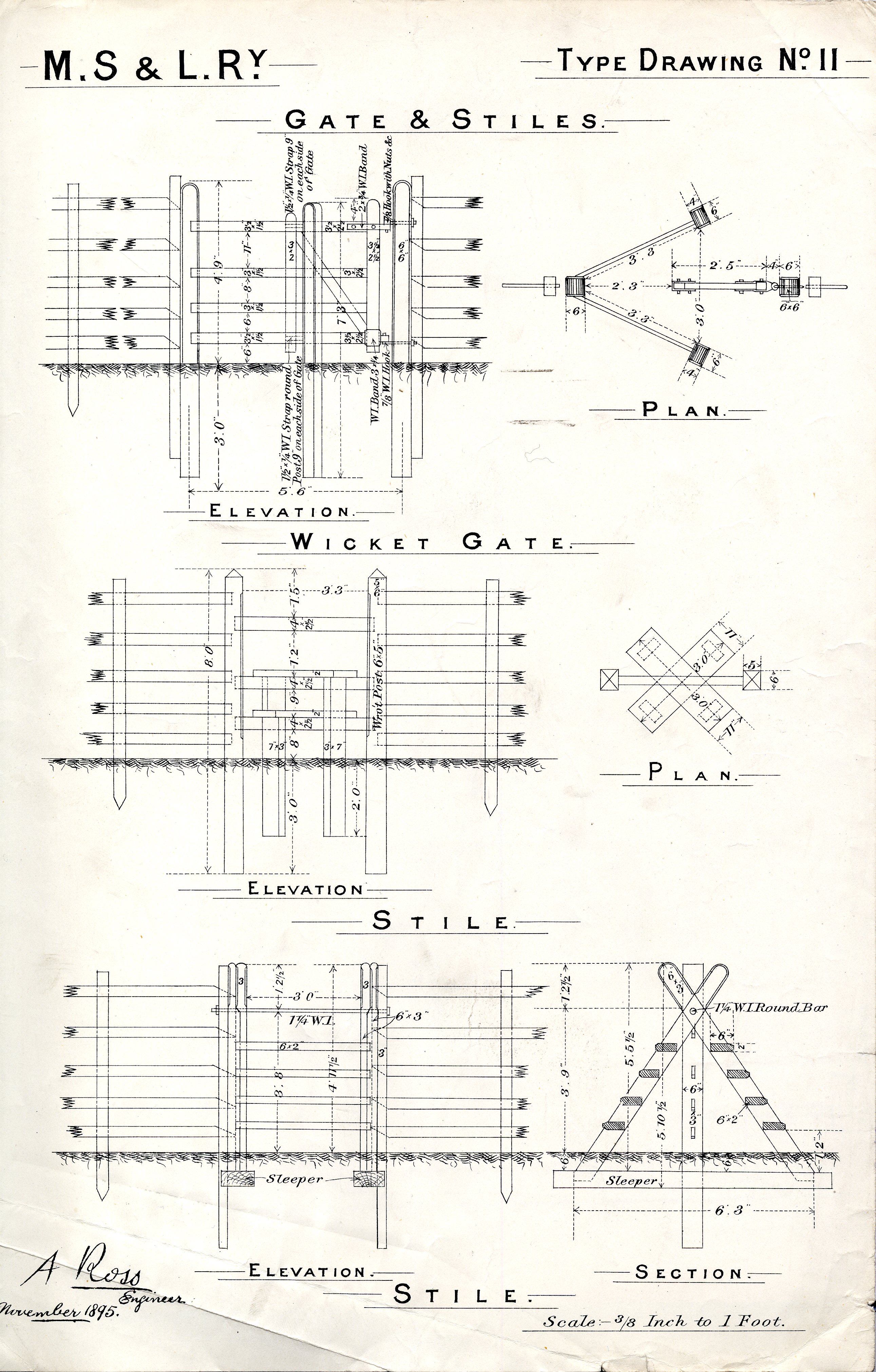
Type Drawing No. 11
Gate & Stiles
Wicket Gate
Stile No. 1
Stile No. 2
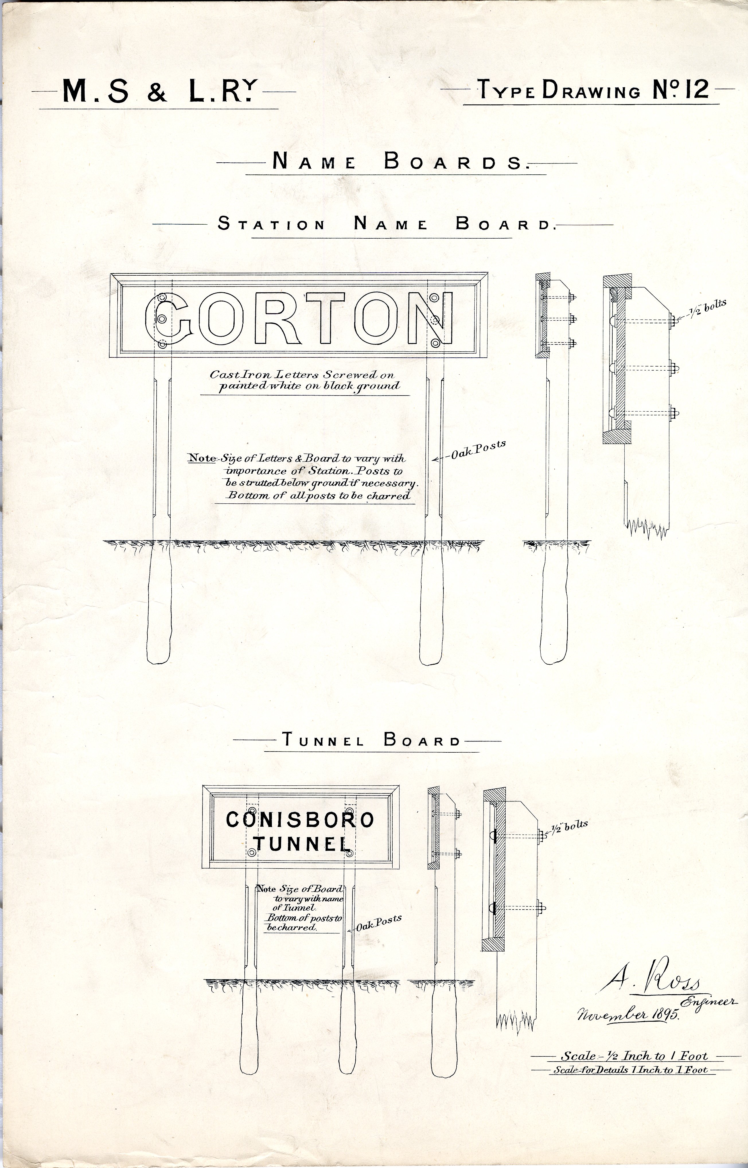
Type Drawing No. 12
Name Boards
Station Name Board
Tunnel Name Board
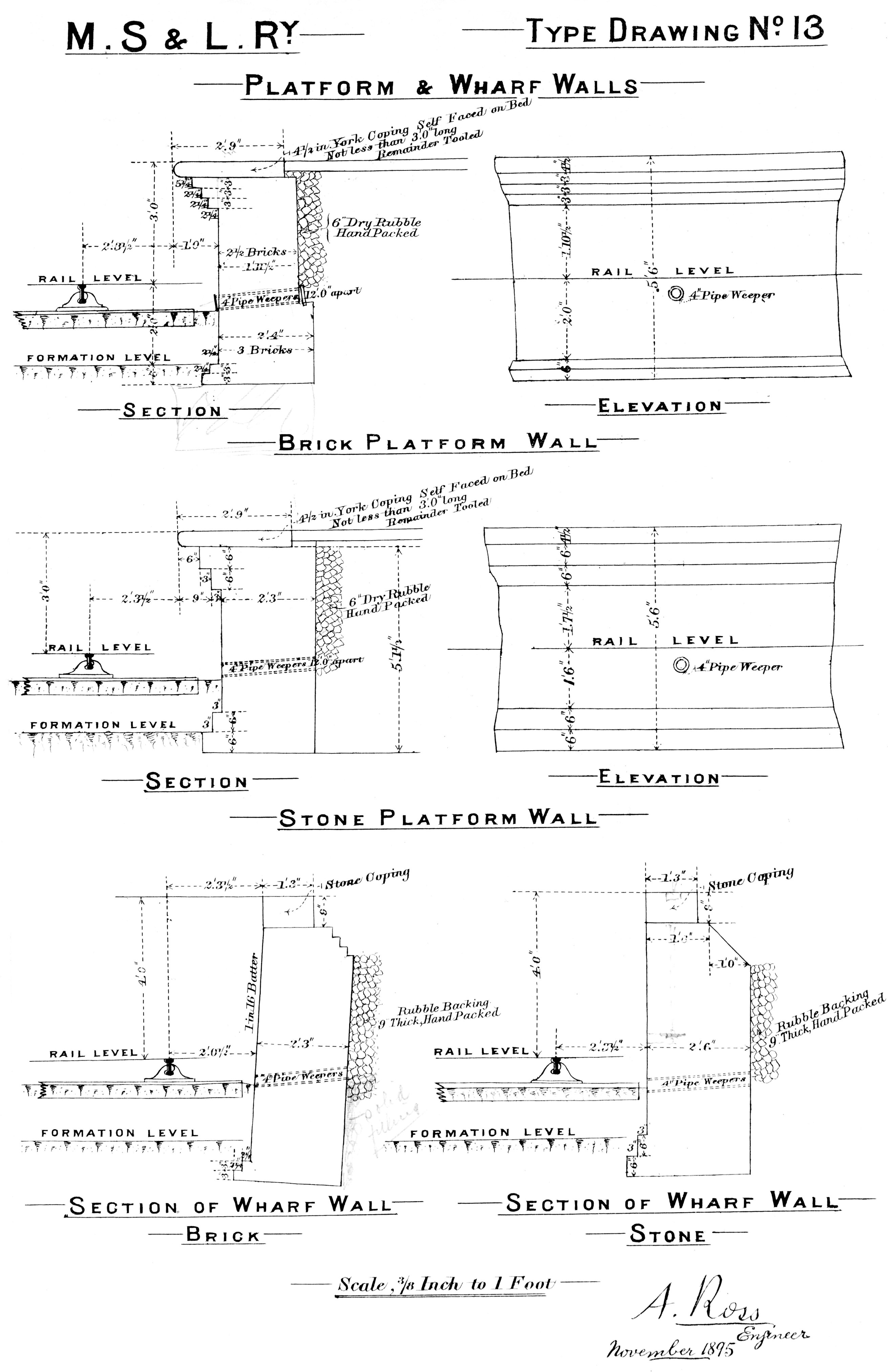
Type Drawing No. 13
Platform and Wharf Walls
Brick Platform Walls
Stone Platform Walls
Sections
Image courtesy of Mr. Steve Taylor
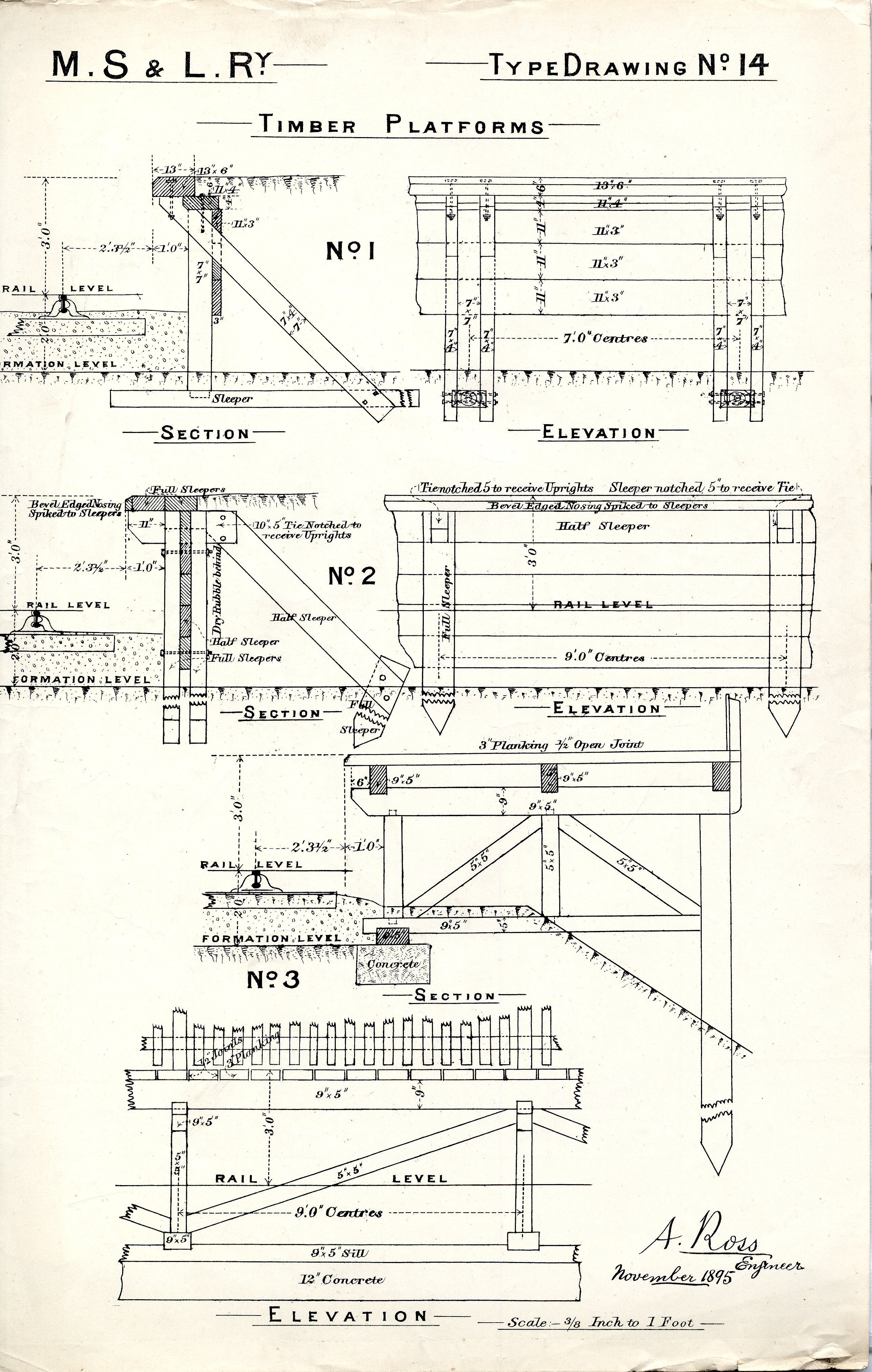
Type Drawing No. 14
Timber Platforms
No. 1
No. 2
No. 3
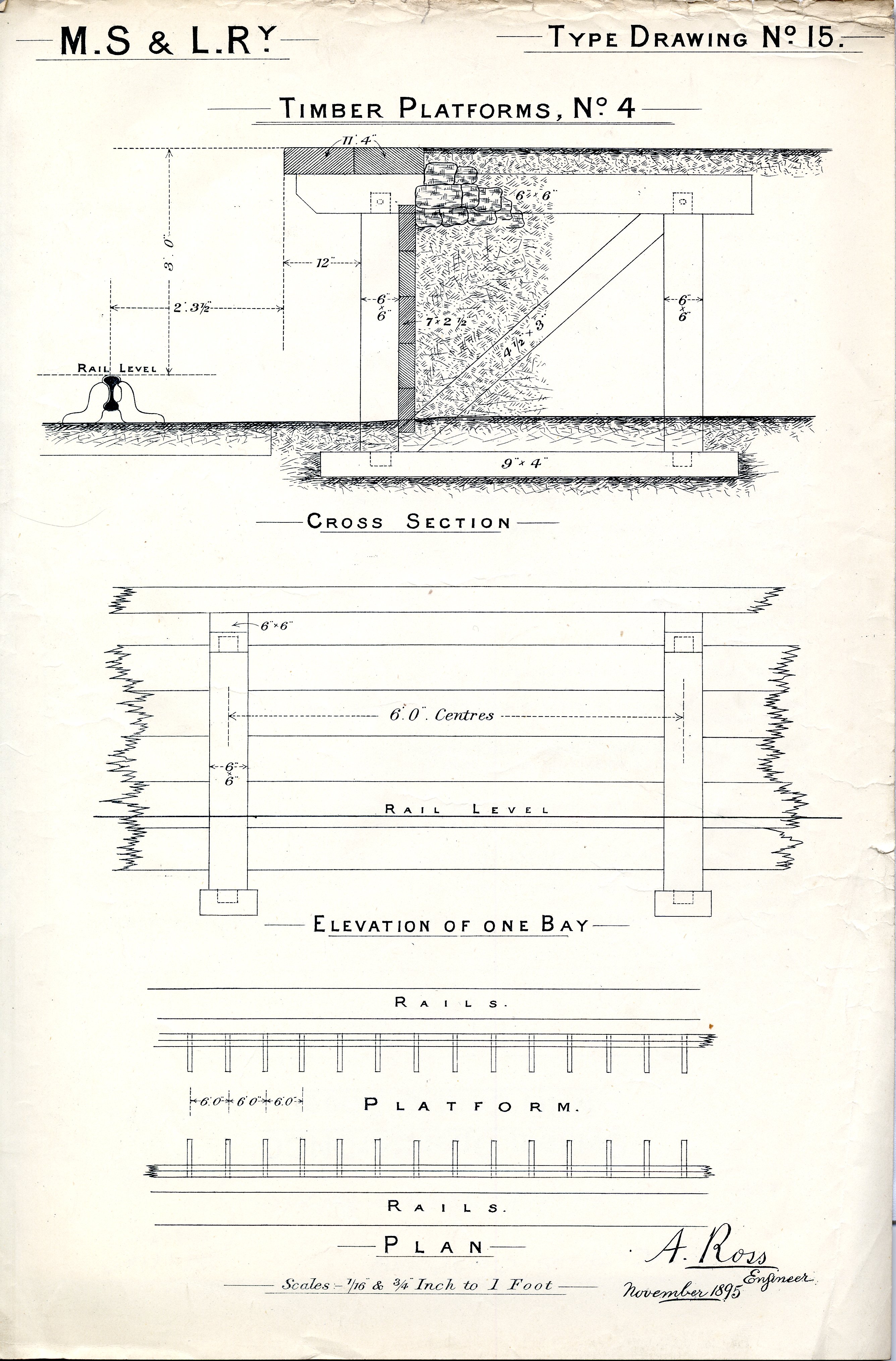
Type Drawing No. 15
Timber Platforms
No. 4
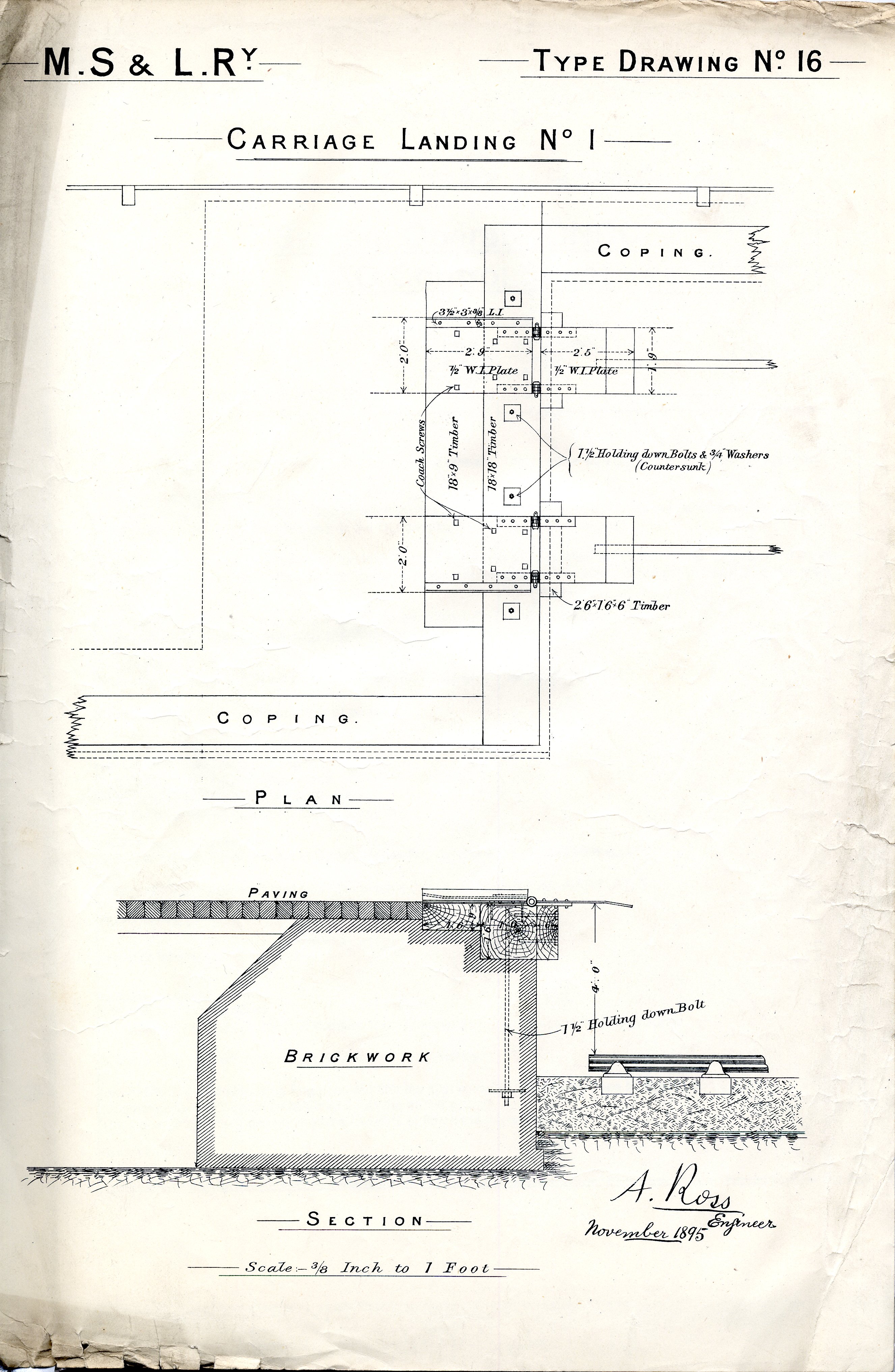
Type Drawing No. 16
Carriage Landing No. 1
Plan
Section

Type Drawing No. 17
Carriage Landing No. 2
Half Sectional Plan
Half Front Elevation
Section
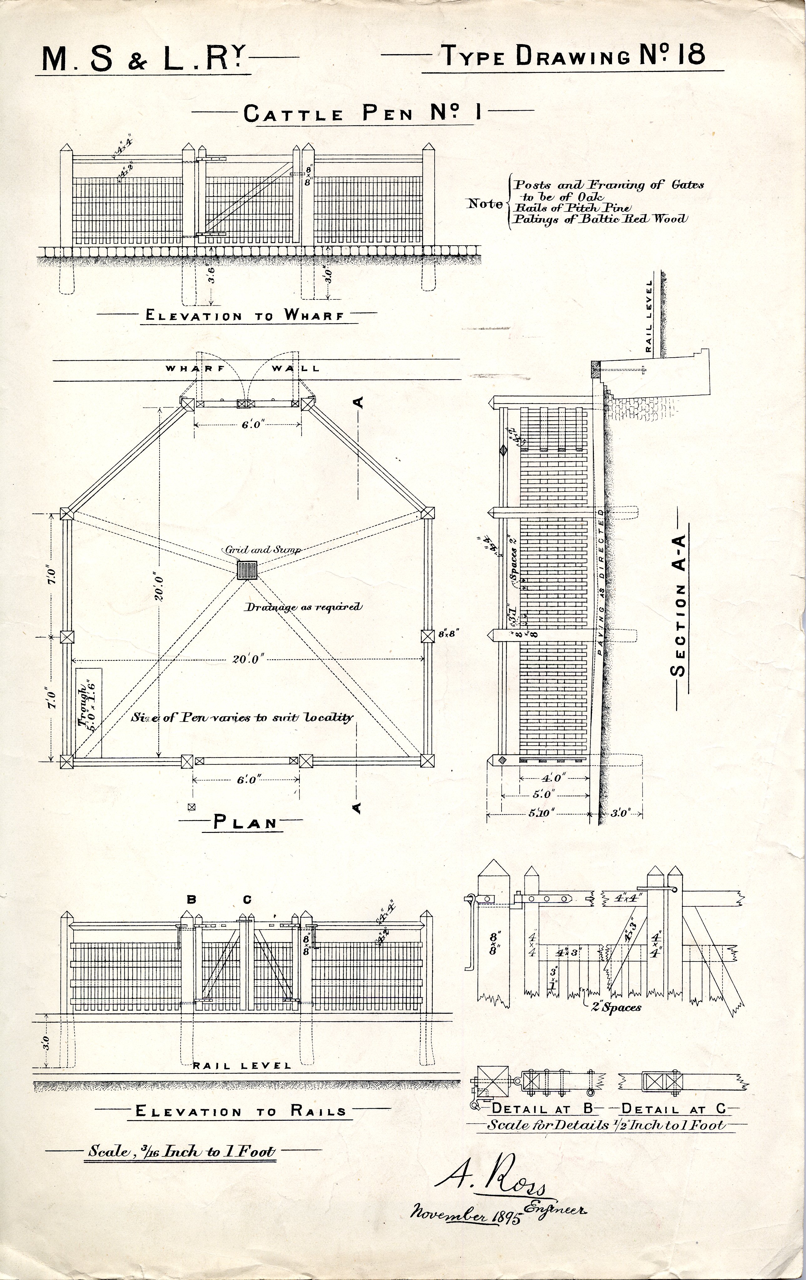
Type Drawing No. 18
Cattle Pen No. 1
Elevation to Wharf
Plan
Elevation to Rails
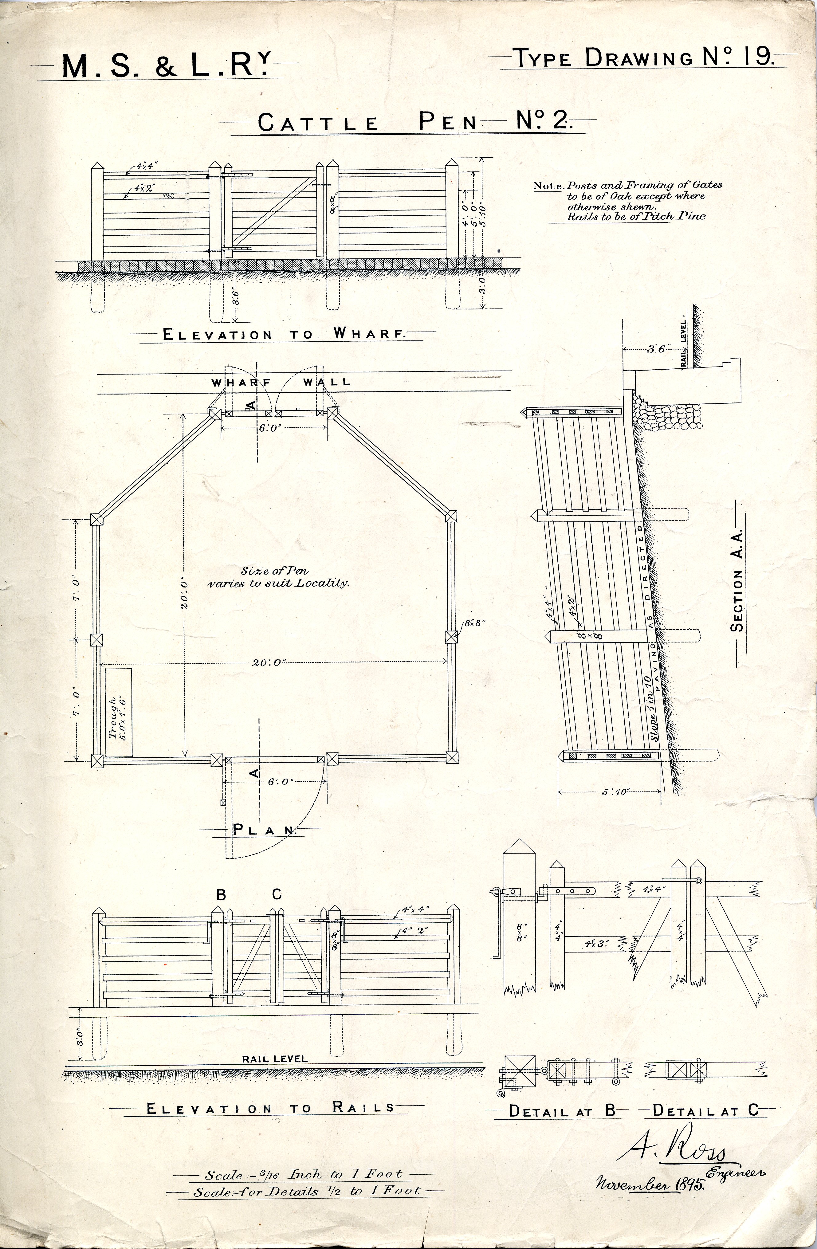
Type Drawing No. 19
Cattle Pen No. 2
Elevation to Wharf
Plan
Elevation to Rails
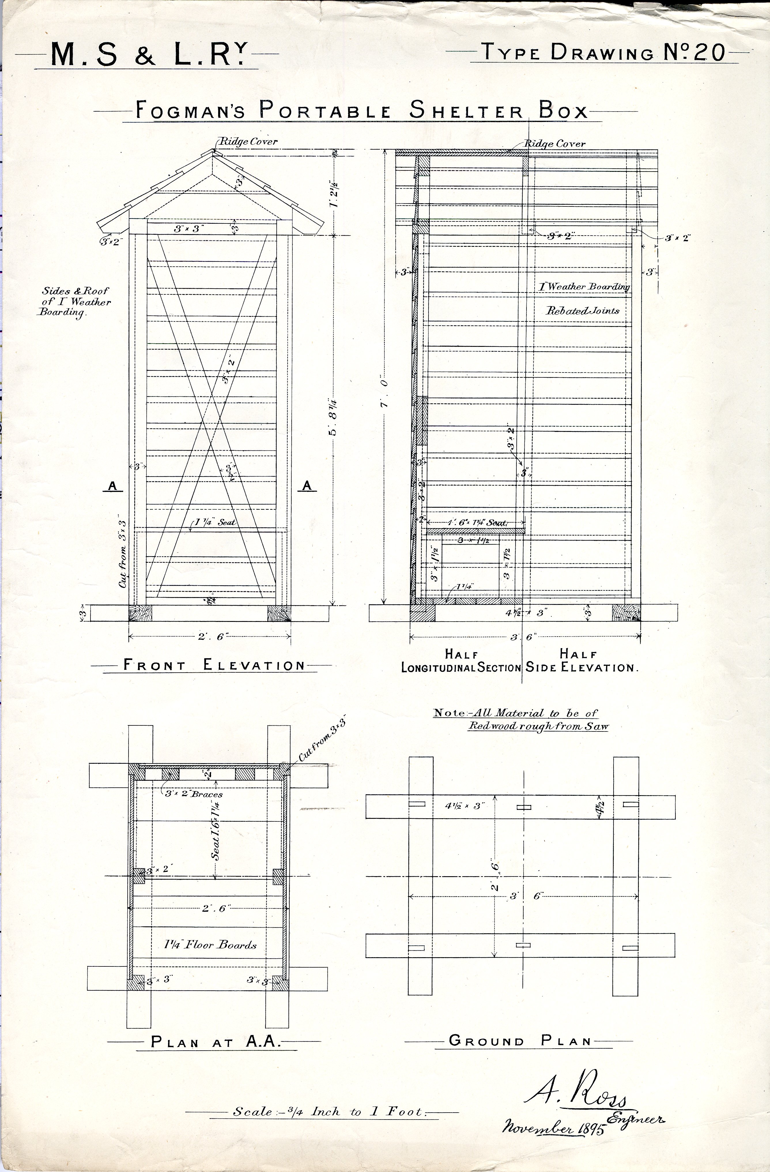
Type Drawing No. 20
Fogman's Portable Shelter Box
Front Elevation
Half Longtitudinal Section / Half Side Elevation
Plan
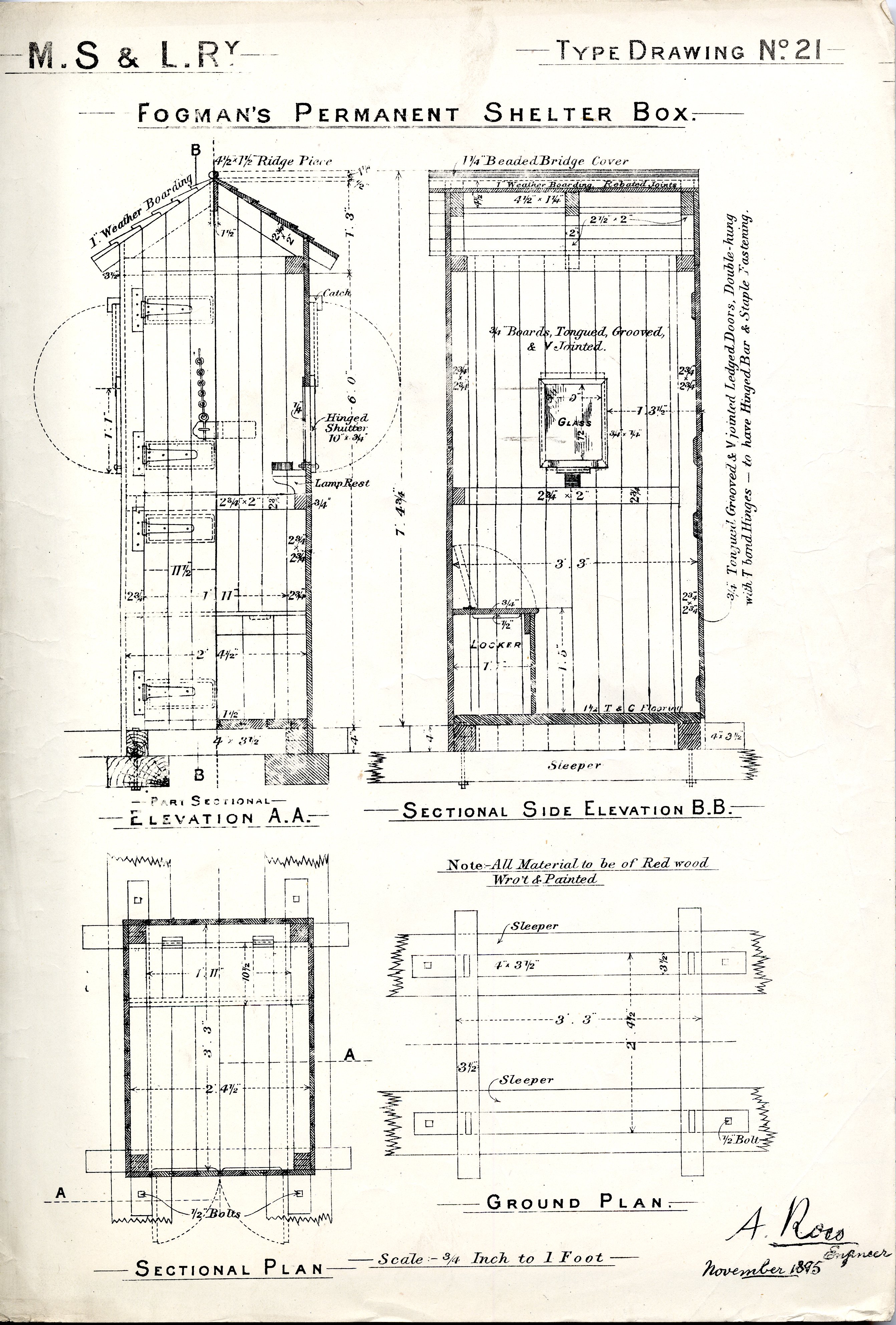
Type Drawing No. 21
Fogman's Permanent Shelter Box
Elevation
Sectional Side Elevation
Sectional Plan
Ground Plan
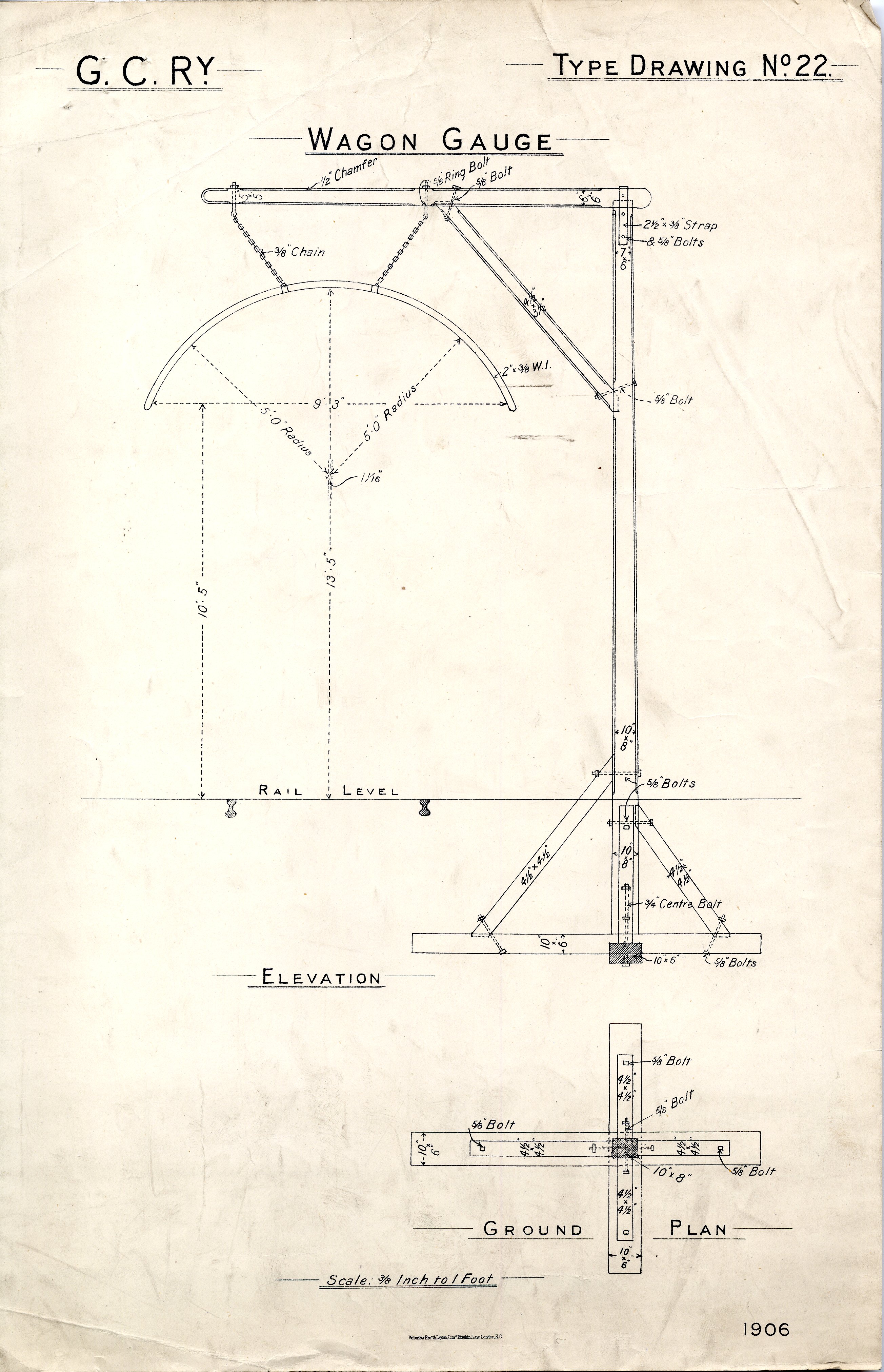
Type Drawing No. 22
Wagon Gauge
Elevation
Ground Plan
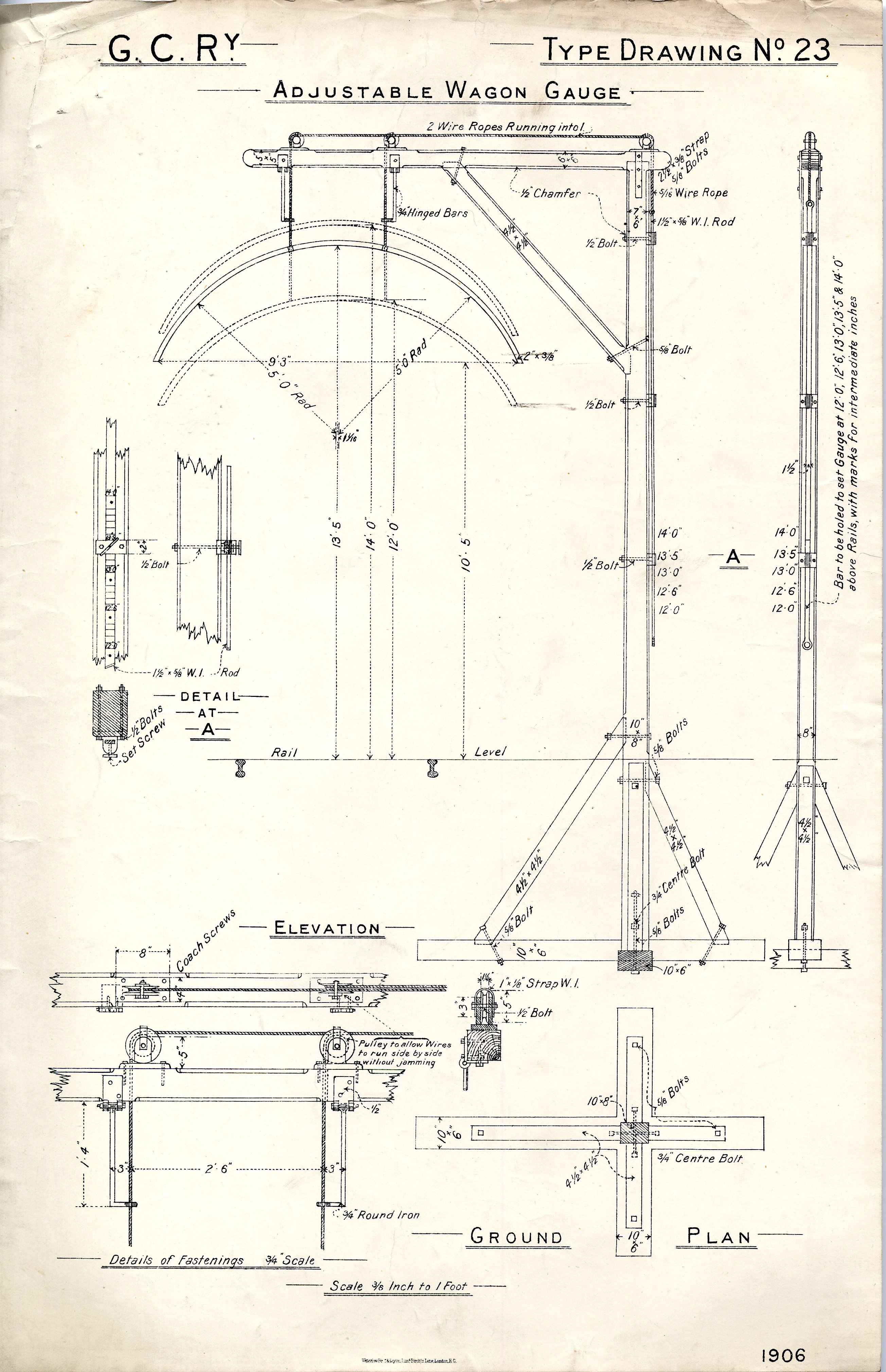
Type Drawing No. 23
Adjustable Wagon Gauge
Elevation
Ground Plan
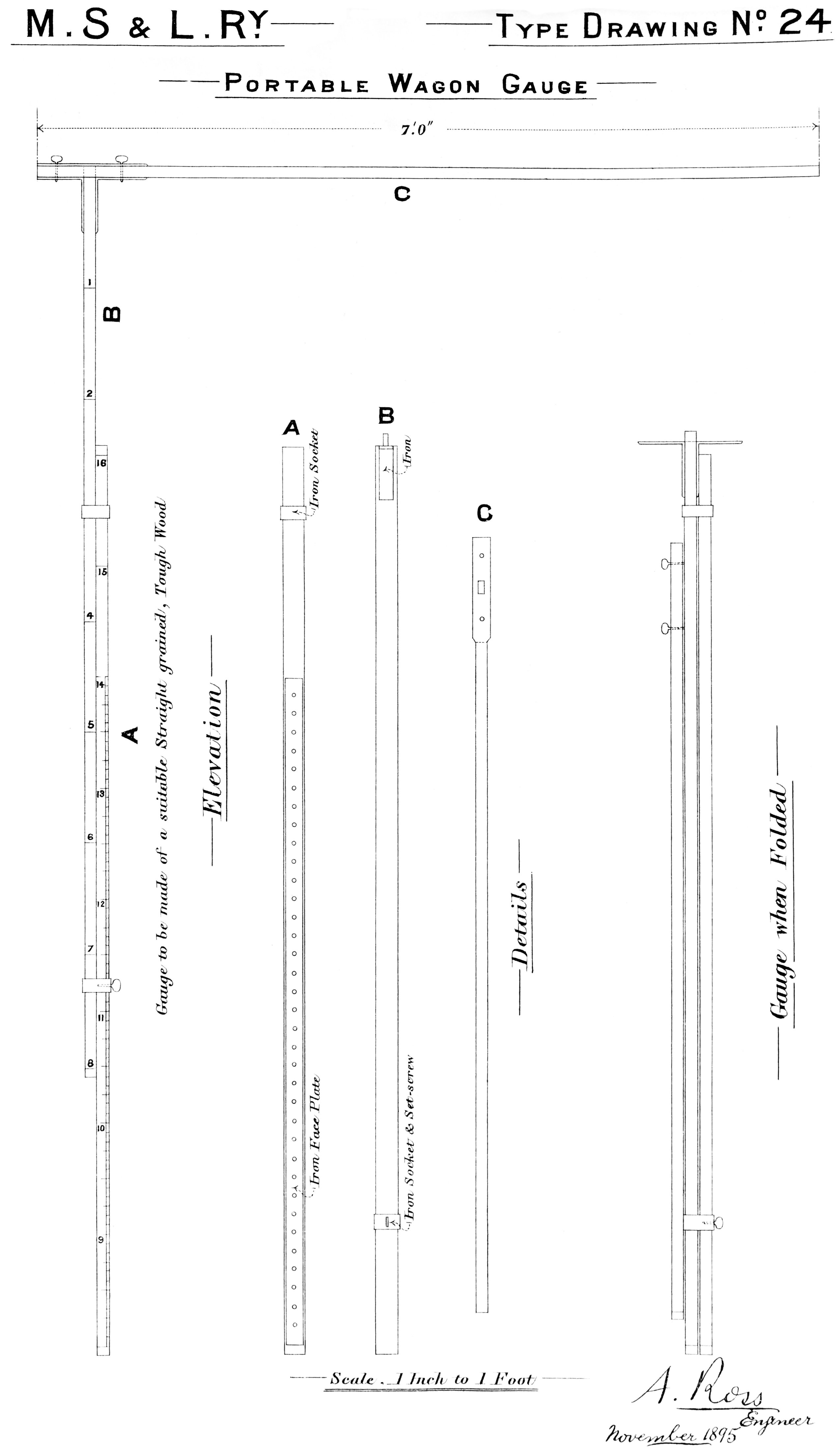
Portable Wagon Gauge
Elevation
Details
Gauge When Folded
Image courtesy of Mr. Steve Taylor
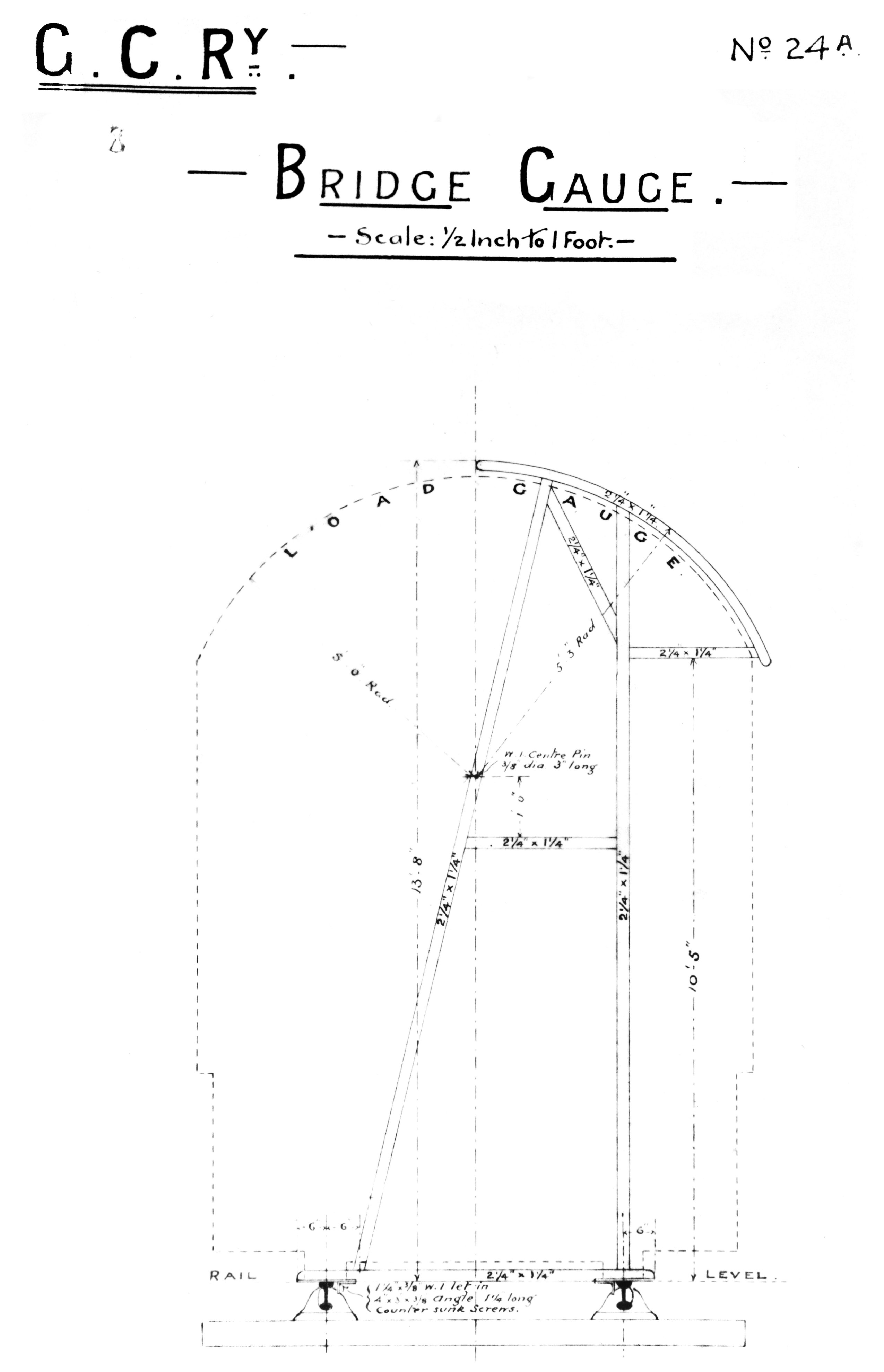
Bridge Gauge
Image courtesy of Mr. Steve Taylor
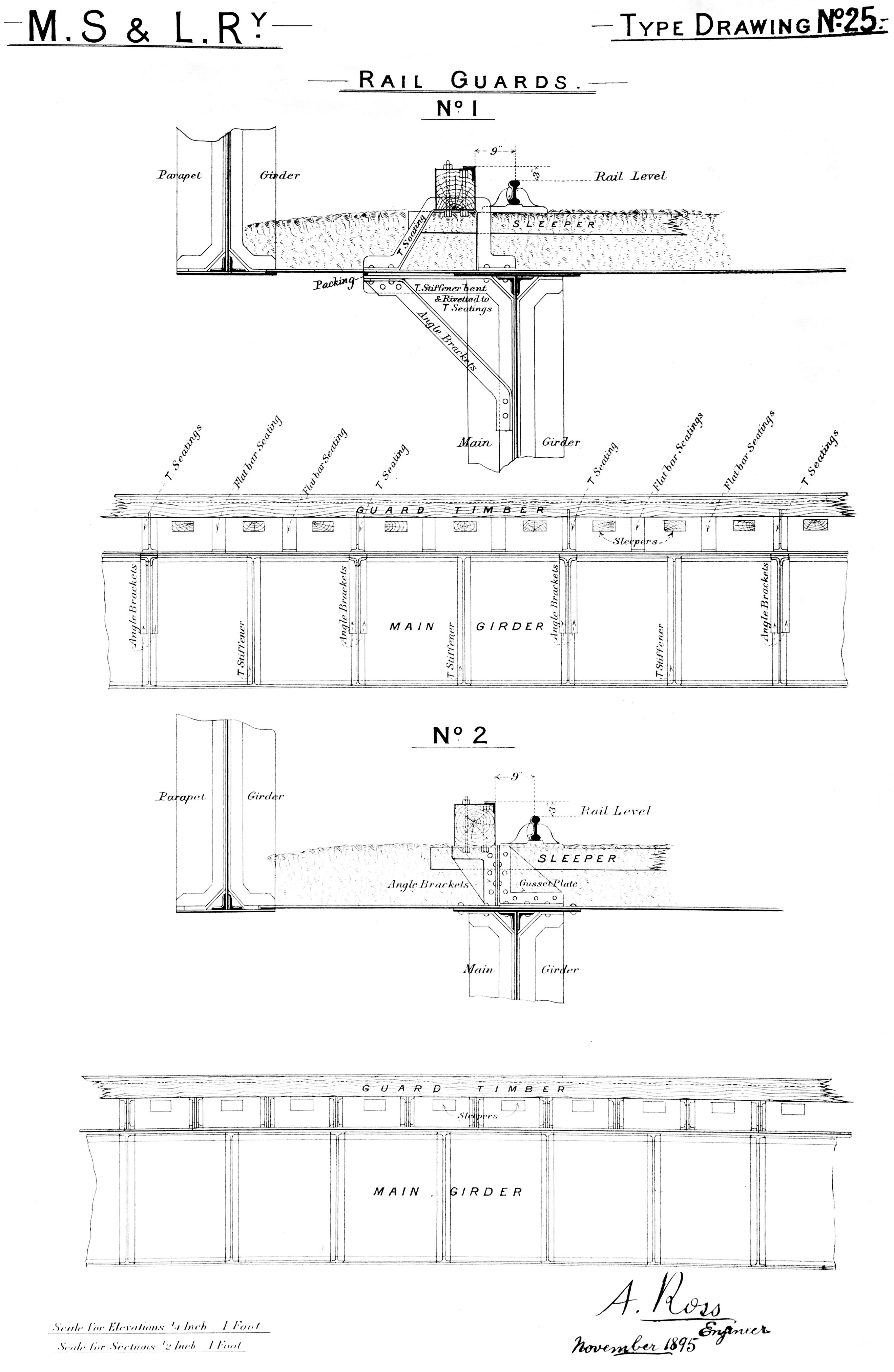
Rail Guards
No. 1
No. 2
Image courtesy of Mr. Steve Taylor

Rail Guards
No. 3
No. 4
Image courtesy of Mr. Steve Taylor
![]()
Clearance Diagram
Structure Gauge
Amended 3rd December 1904 on instructions of J. G. Robinson
Image courtesy of Mr. Steve Taylor
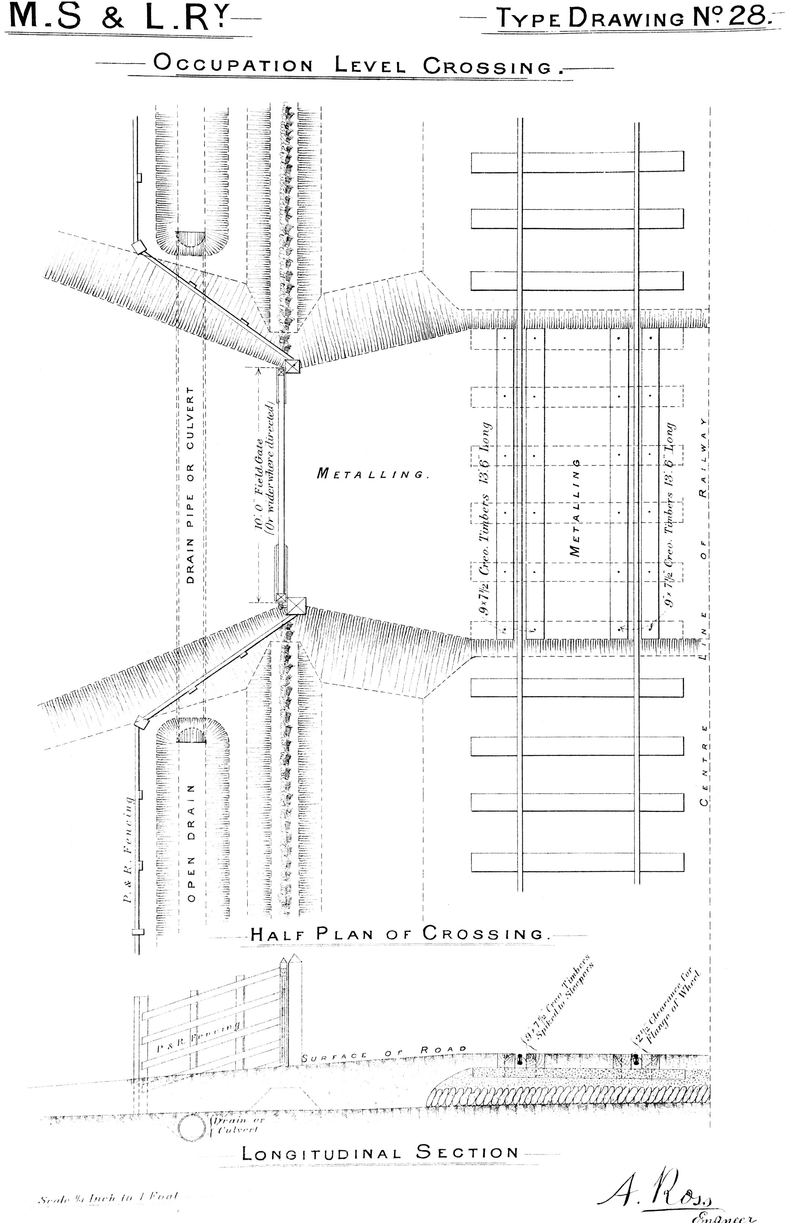
Occupation Level Crossing
Half plan of crossing
Longitudinal section
Image courtesy of Mr. Steve Taylor
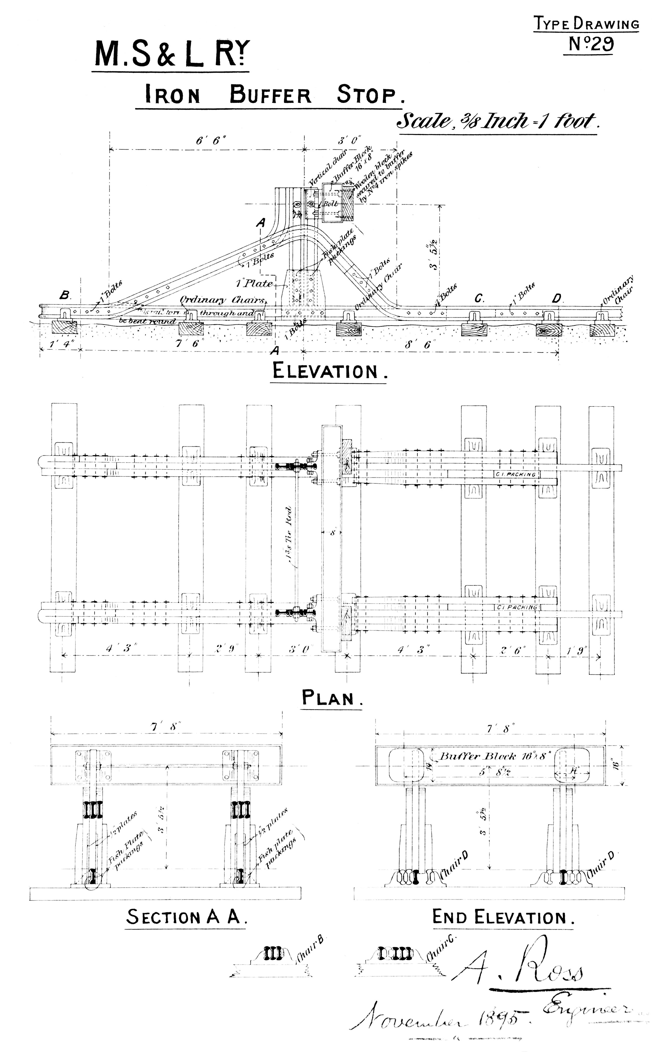
Type Drawing No. 29
Iron Buffer Stop
Elevation
Plan
Section
Image courtesy of Mr. Steve Taylor
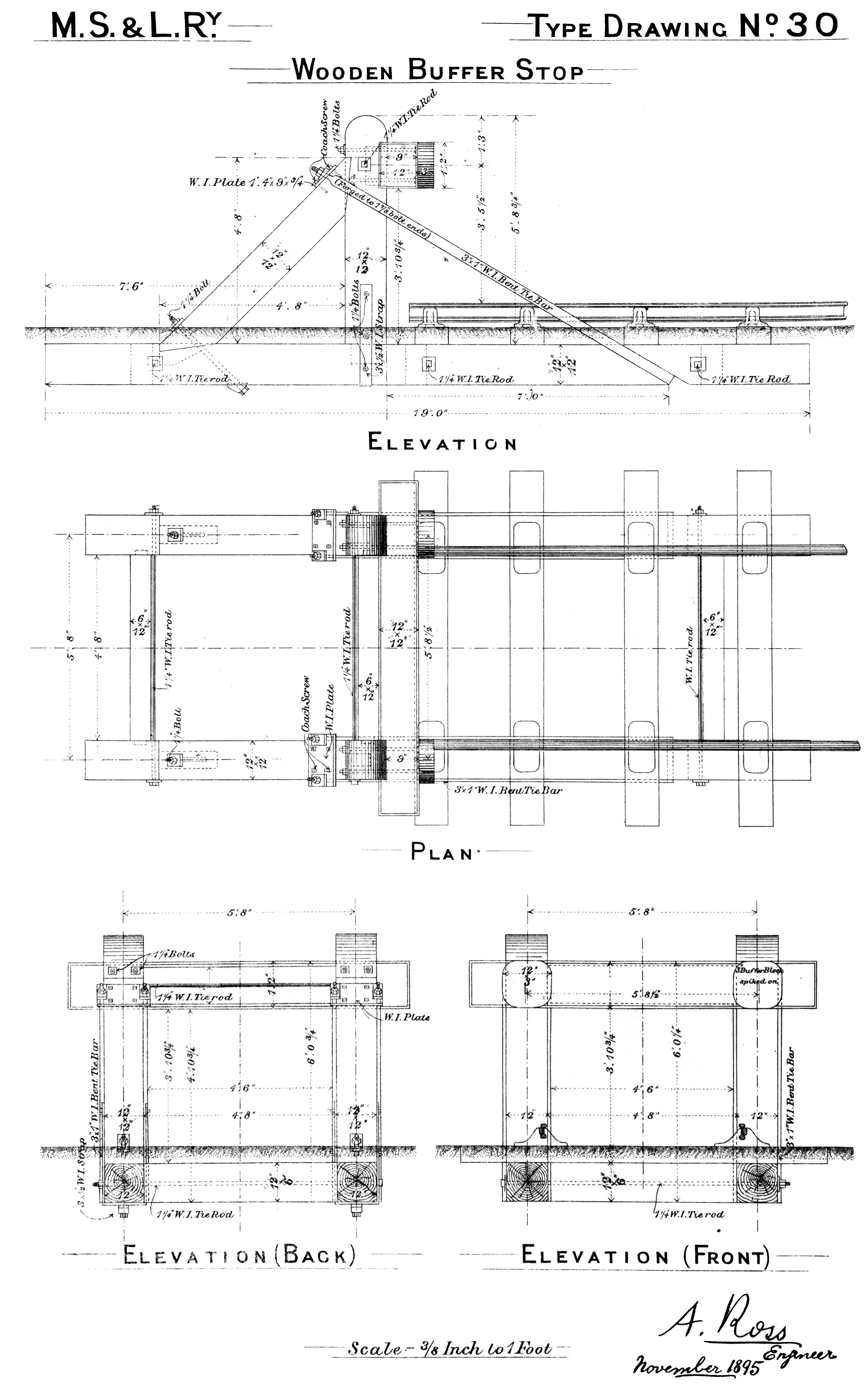
Type Drawing No. 30
Wooden Buffer Stop
Elevation
Plan
Elevation (Back)
Elevation (Front)
Image courtesy of Mr. Steve Taylor
![]()
Hydraulic Buffic Stop
![]()
![]()
![]()
![]()
![]()
![]()
![]()
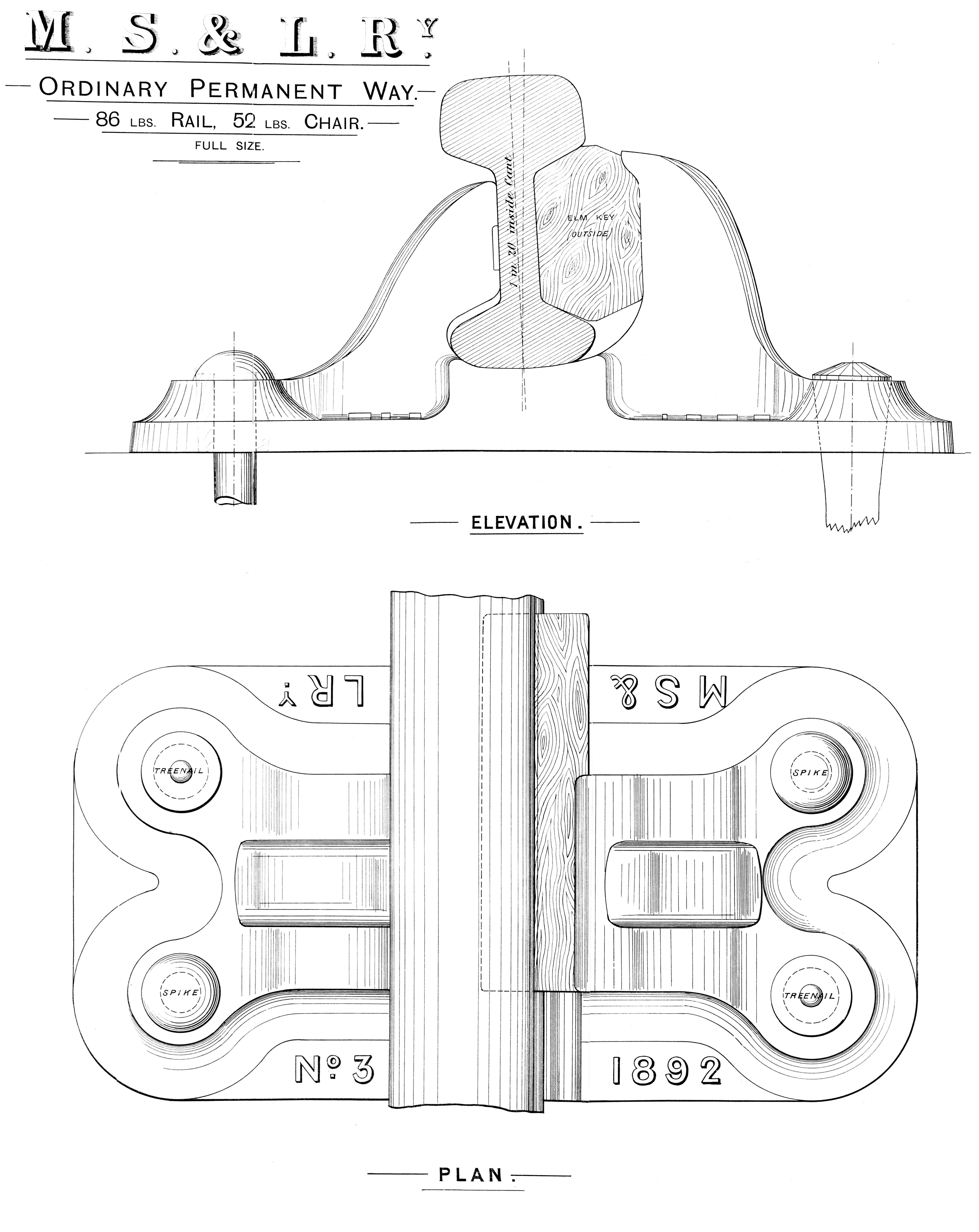
Permanent Way - 52lb Chair
For 86lb rail
Plan
Elevation
Image courtesy of Mr. Steve Taylor
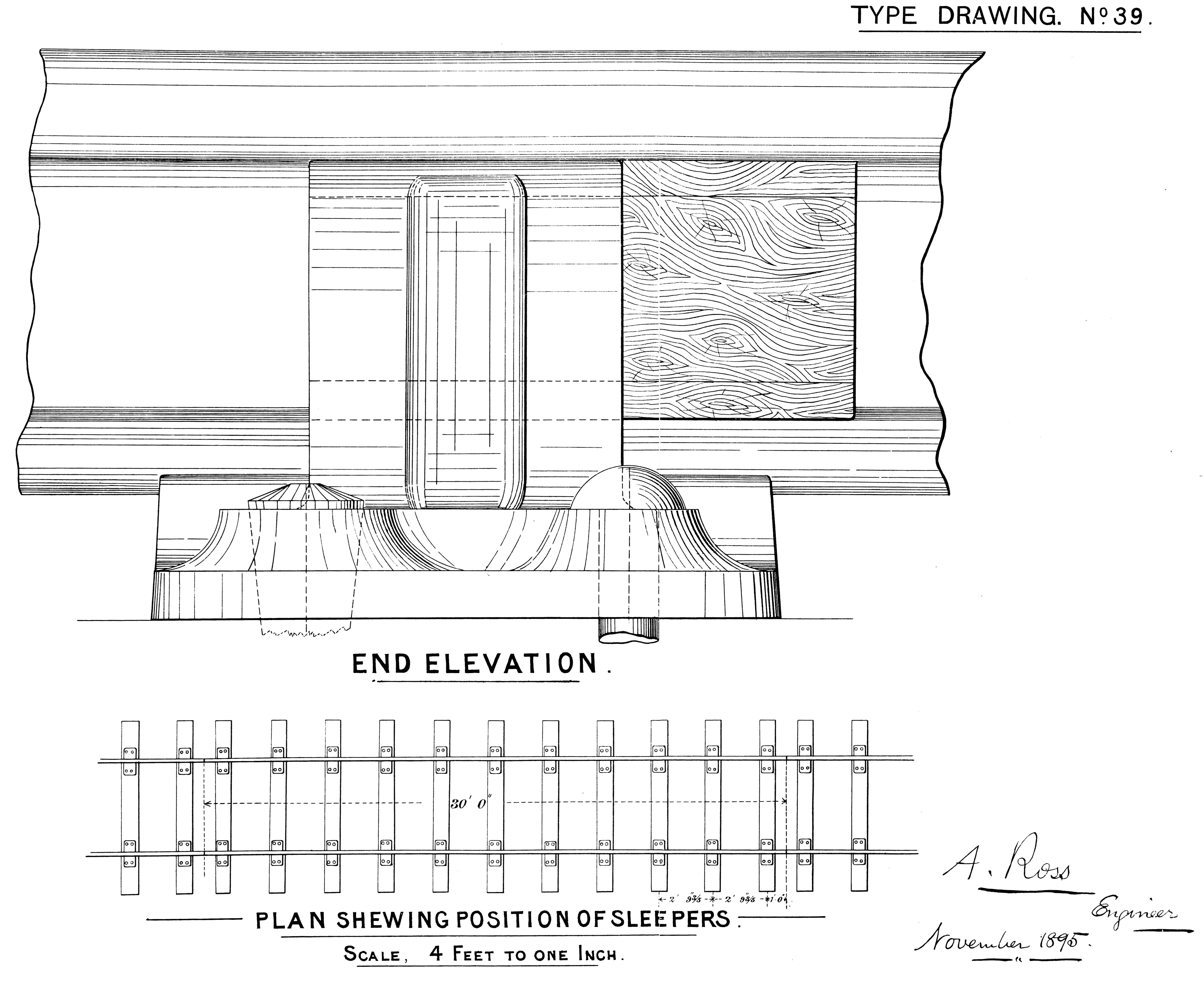
Permanent Way No. 3 Section
86lbs rail & 52lbs chairs
11 sleepers to the 30 foot rail
November 1895
Image courtesy of Mr. Steve Taylor
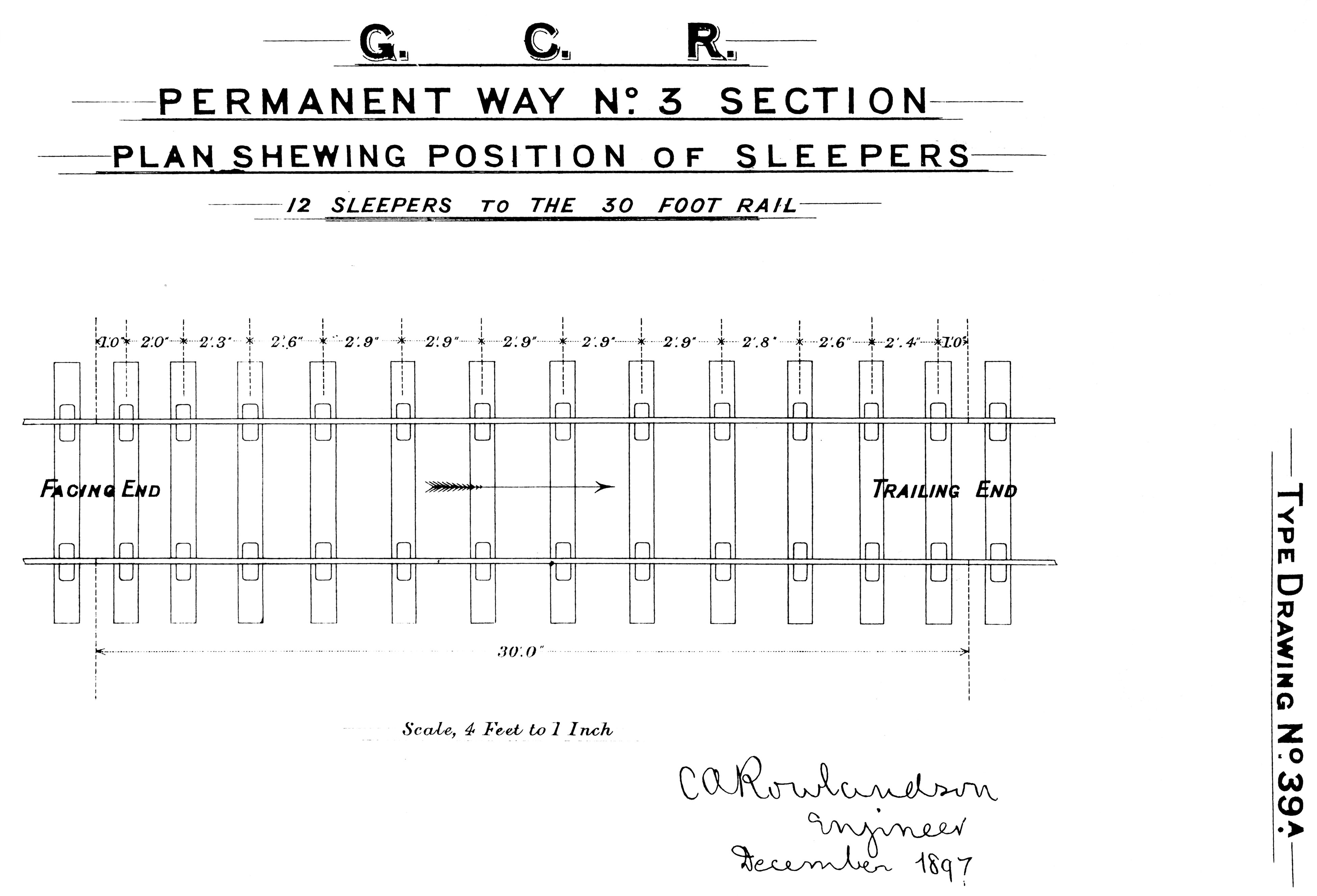
Permanent Way No. 3 Section
Shewing position of sleepers
12 sleepers to the 30 foot rail
December 1897
Image courtesy of Mr. Steve Taylor
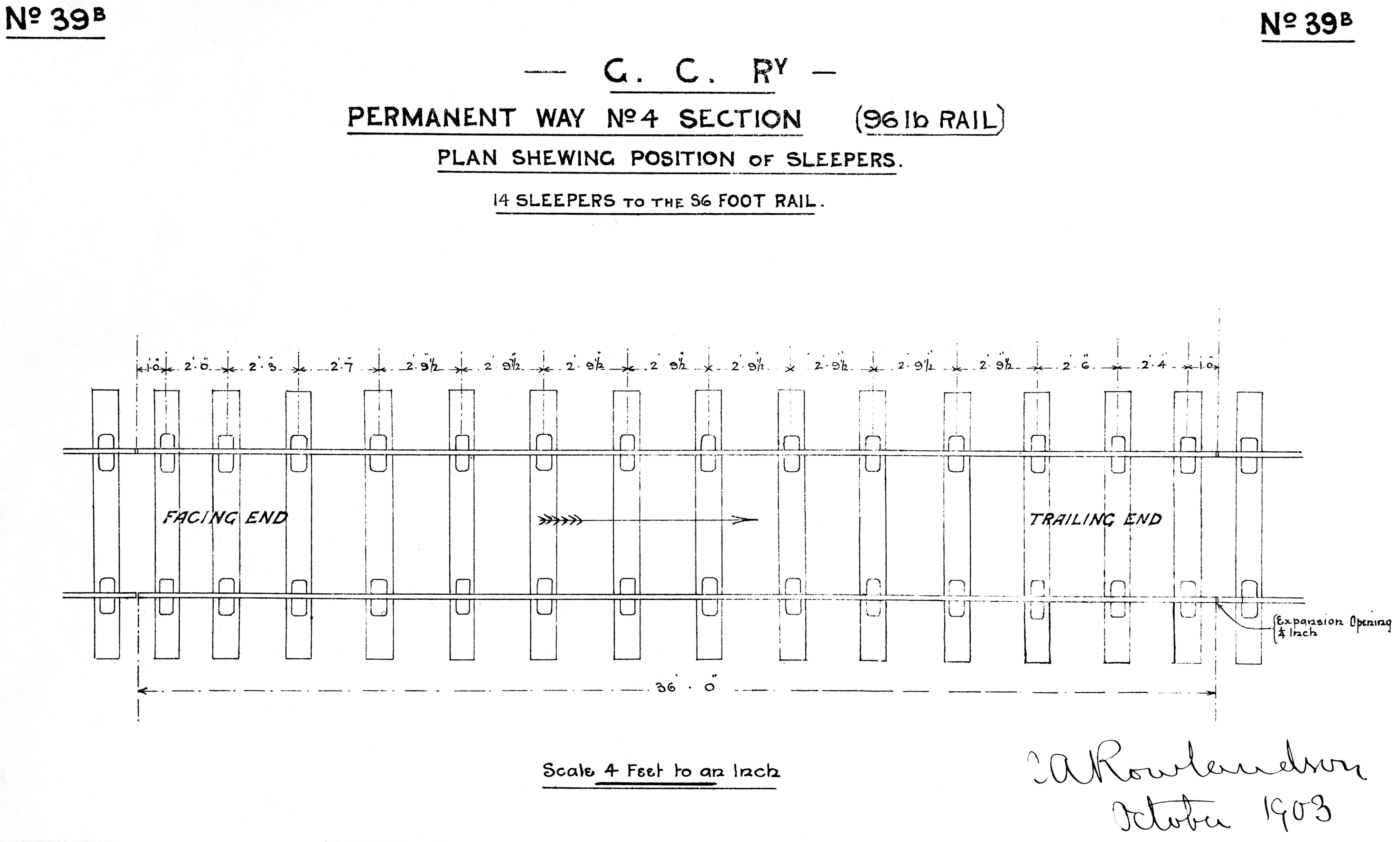
Permanent Way No. 4 Section
Shewing position of sleepers
14 sleepers to the 36 foot rail
October 1903
Image courtesy of Mr. Steve Taylor

Permanent Way - Check Rail Chair
Image courtesy of Mr. Steve Taylor
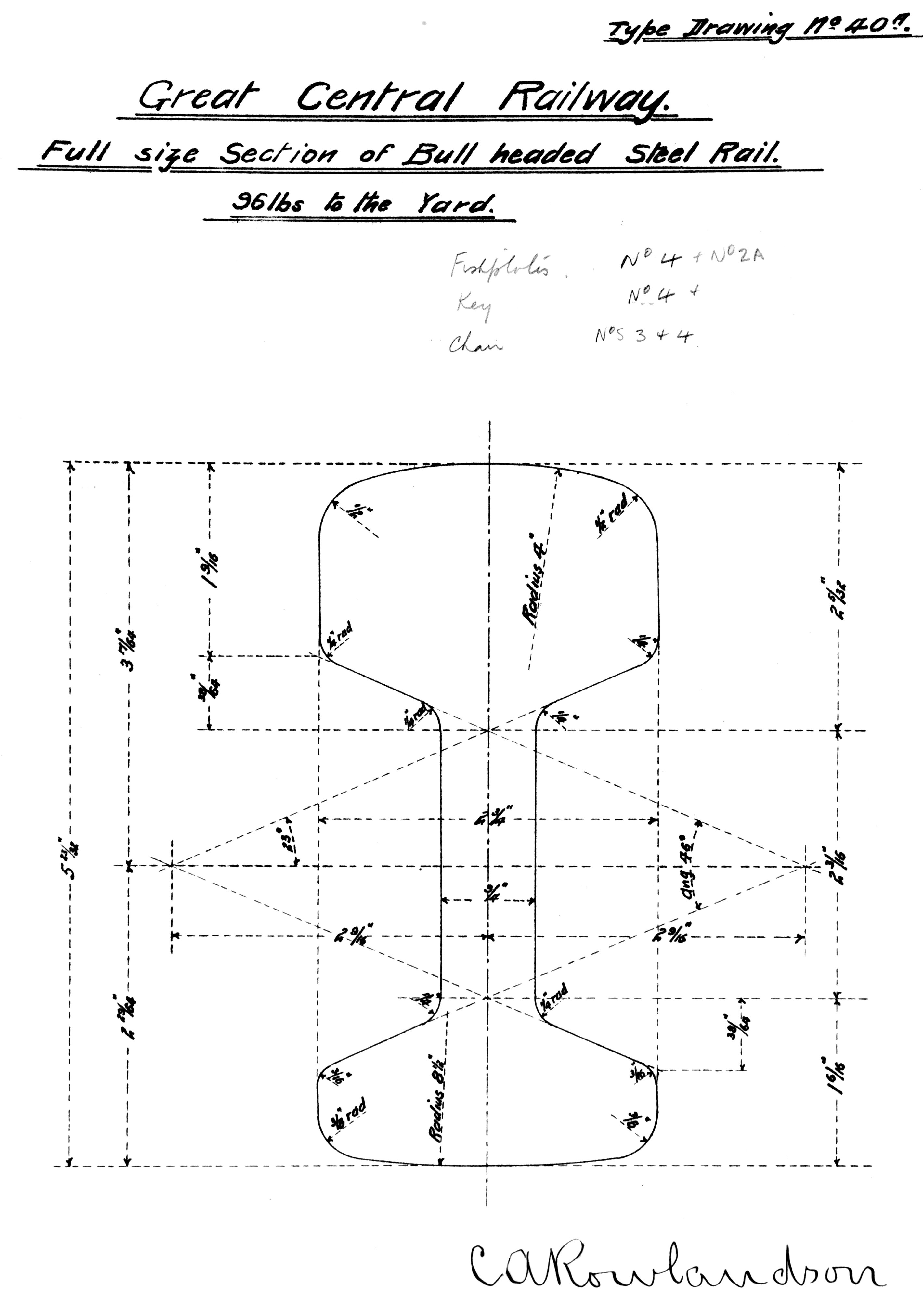
Permanent Way - 96lb Bullhead Rail
Image courtesy of Mr. Steve Taylor
![]()
![]()
![]()
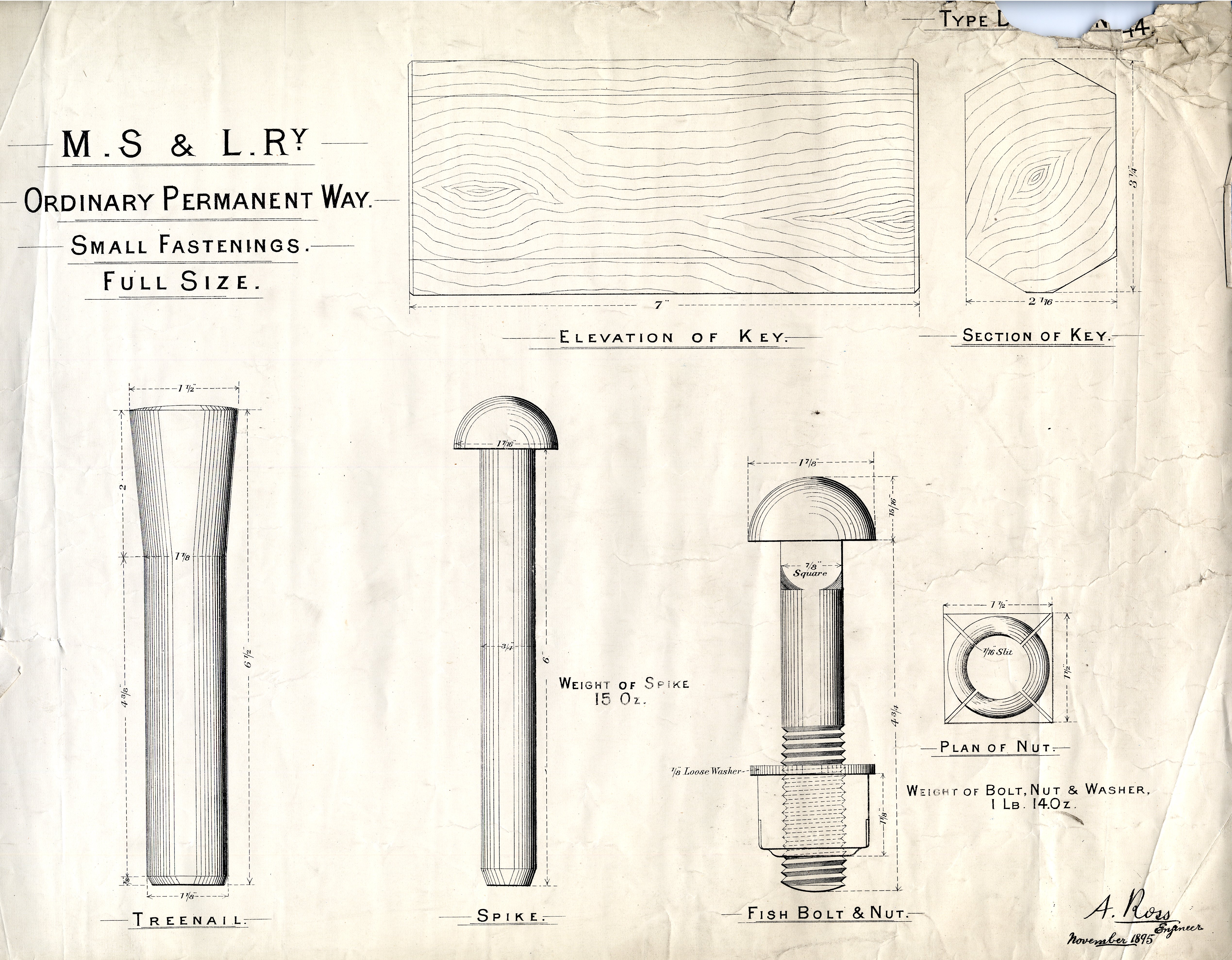
Ordinary Permanent Way - Small Fastenings
Key
Trenail
Fish Bolt & Nut
![]()
Type Drawing No. 45
Gantry
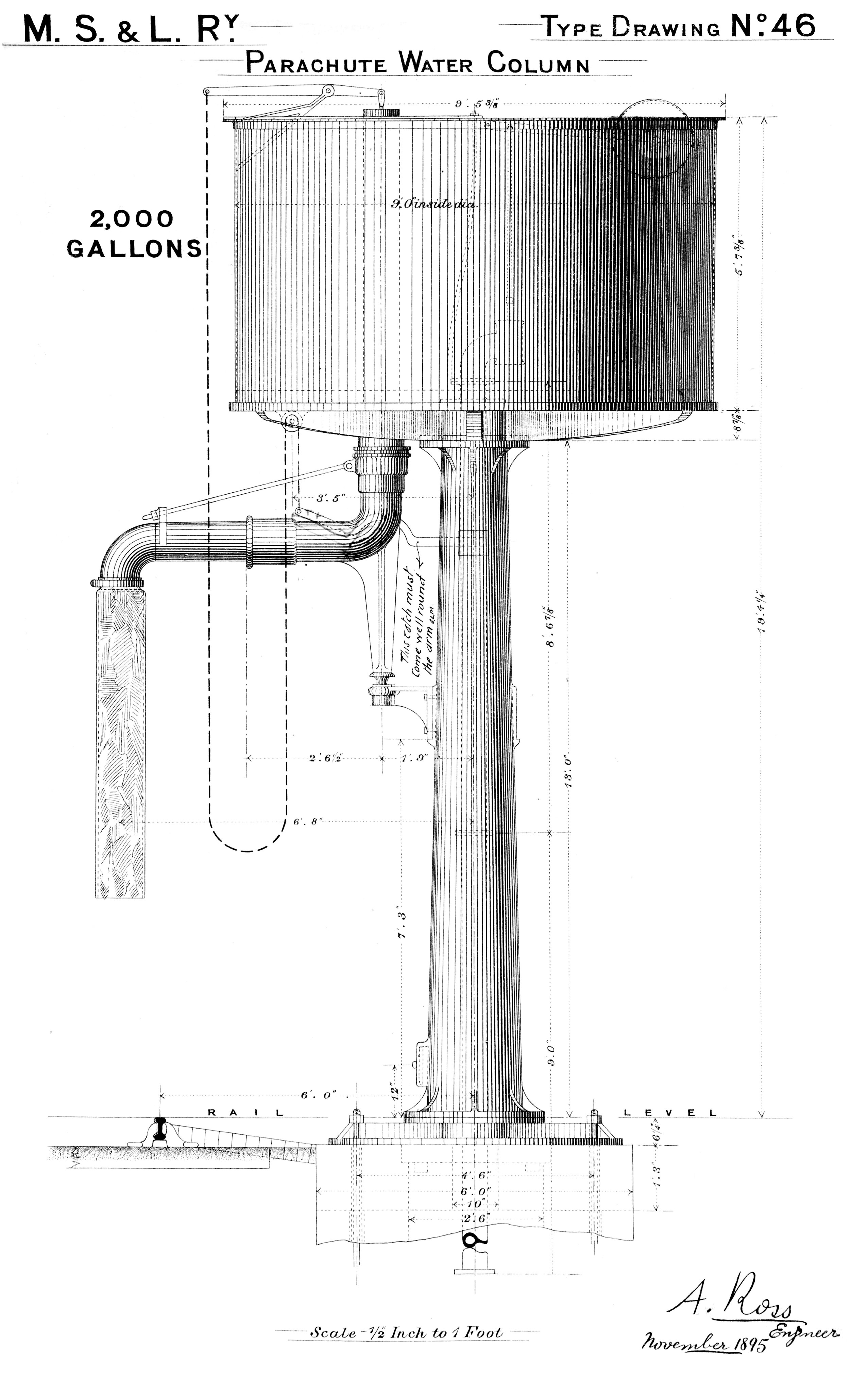
Parachute Water Column
2000 Gallons
Image courtesy of Mr. Steve Taylor
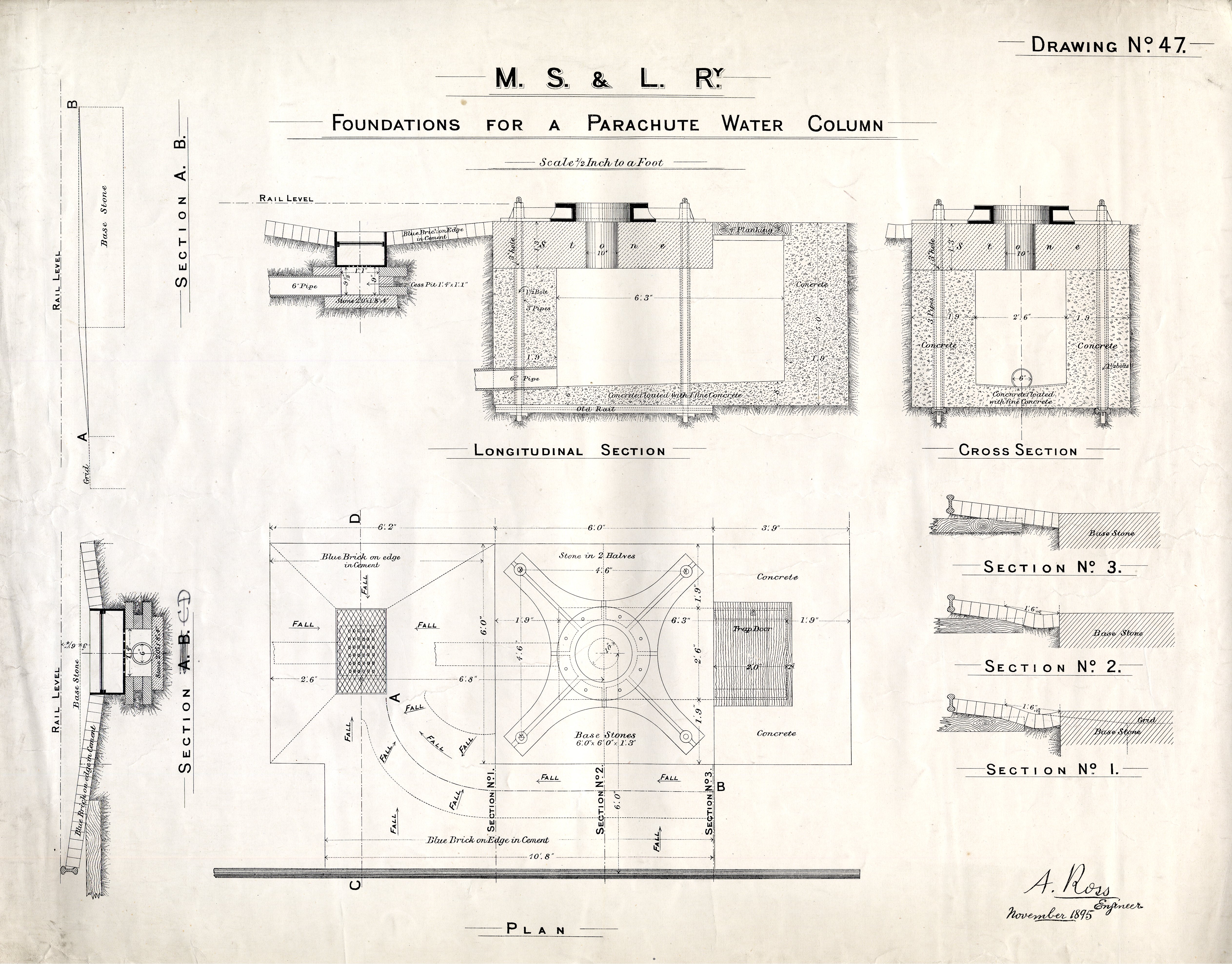
Foundations for a Parachute Water column
Longtitudinal Section
Cross Section
Plan
![]()
Type Drawing No. 48
Parachute Water Column
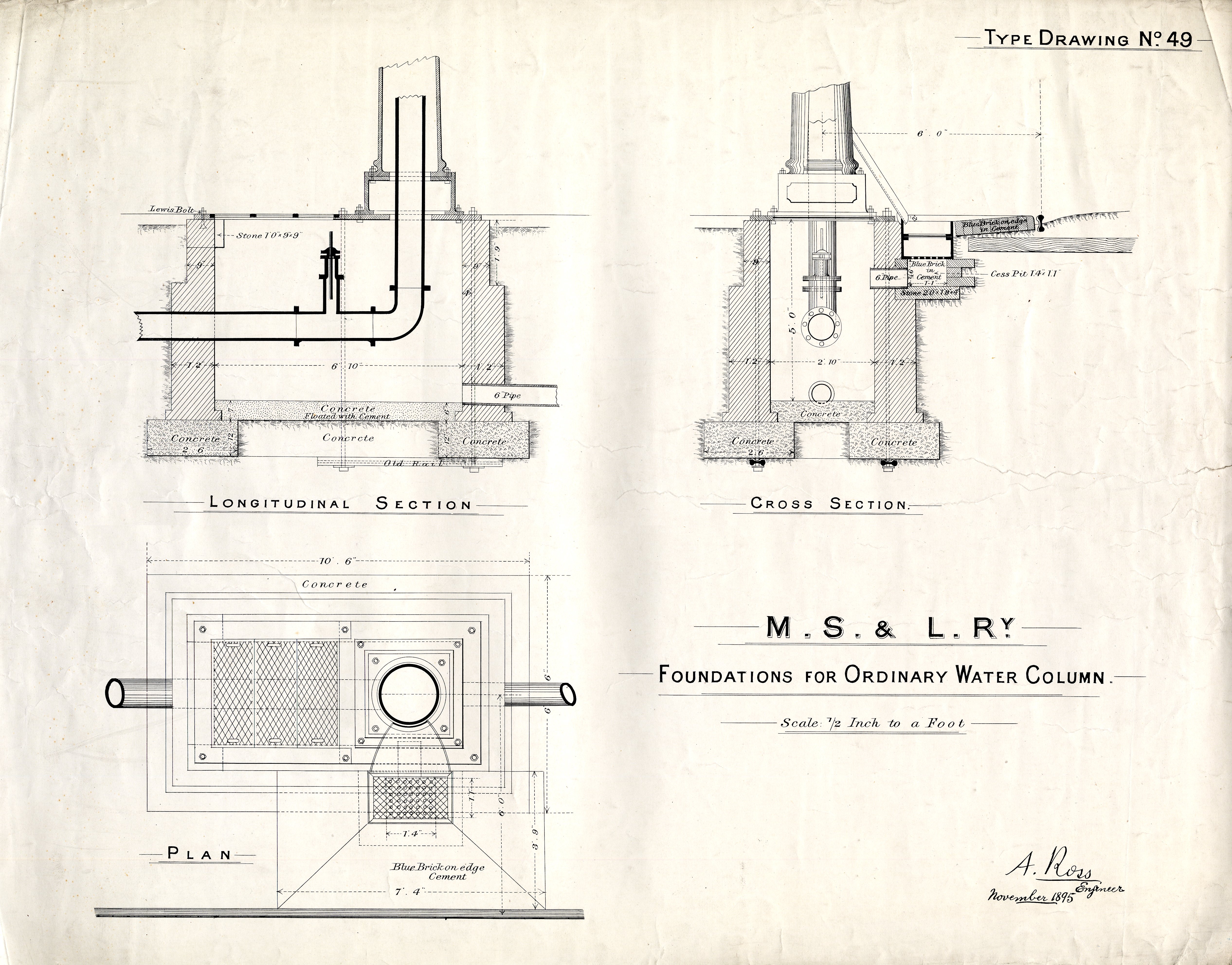
Foundations for Oridinary Water Column
Longtitudinal Section
Cross Section
Plan
![]()
Type Drawing No. 50
Ordinary Water Column
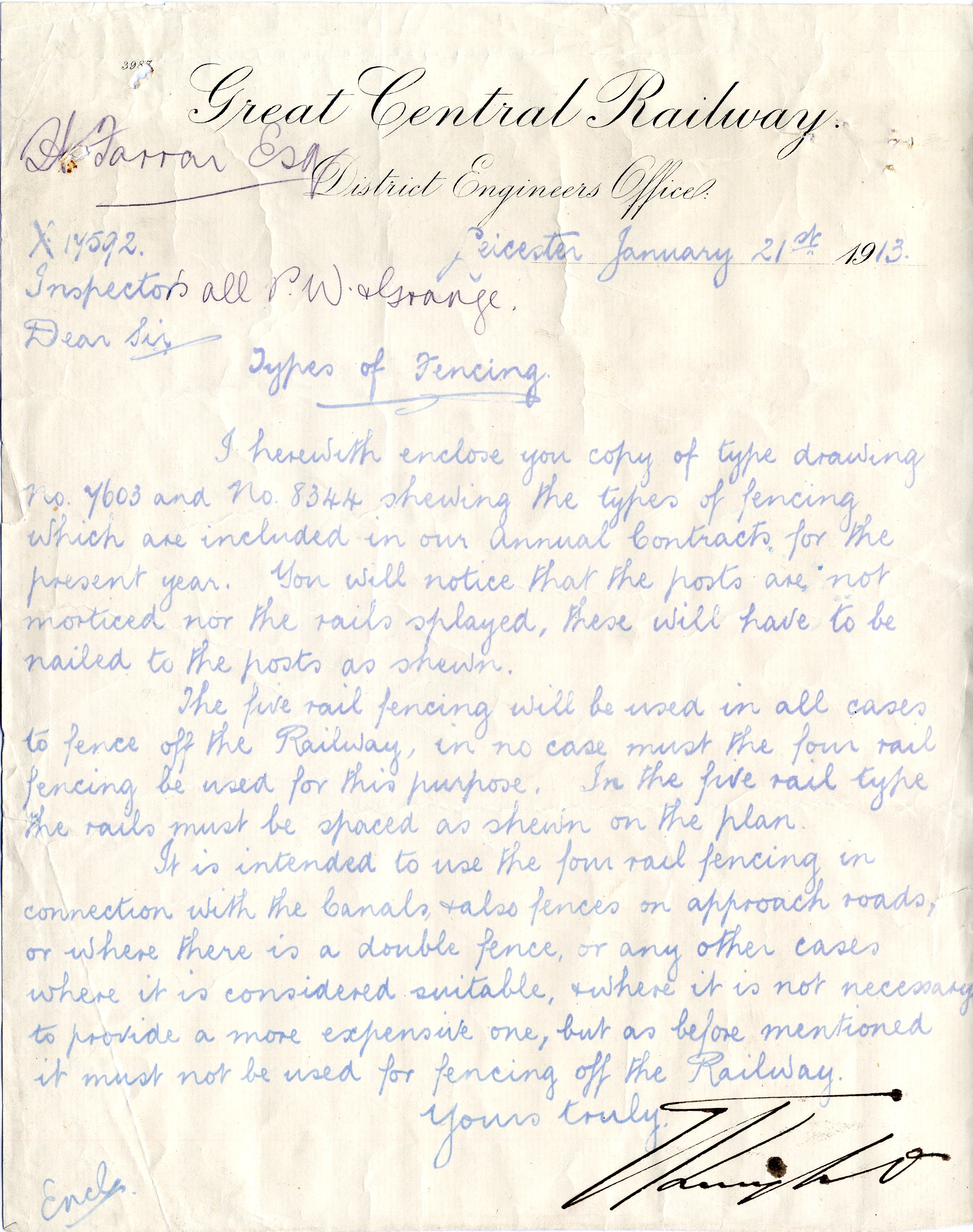
Letter, dated 21st January 1913. From the District Engineer, Leicester, to his Inspectors. It refers to two newly issued Type Drawings for fencing, No. 7603 and No. 8344 (both reproduced below), and gives details of when and where they should be used.

Type Drawing No. 7603
Post & Rail Fence (5 Bar)
Dated 16th February 1912
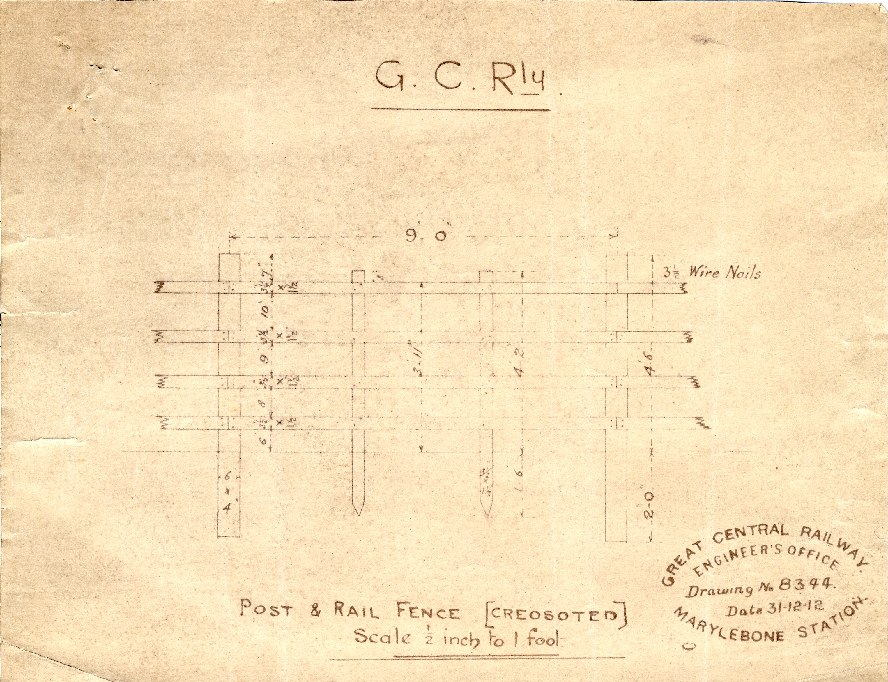
Type Drawing No. 8344
Post & Rail Fence (4 Bar)
Dated 31st December 1912
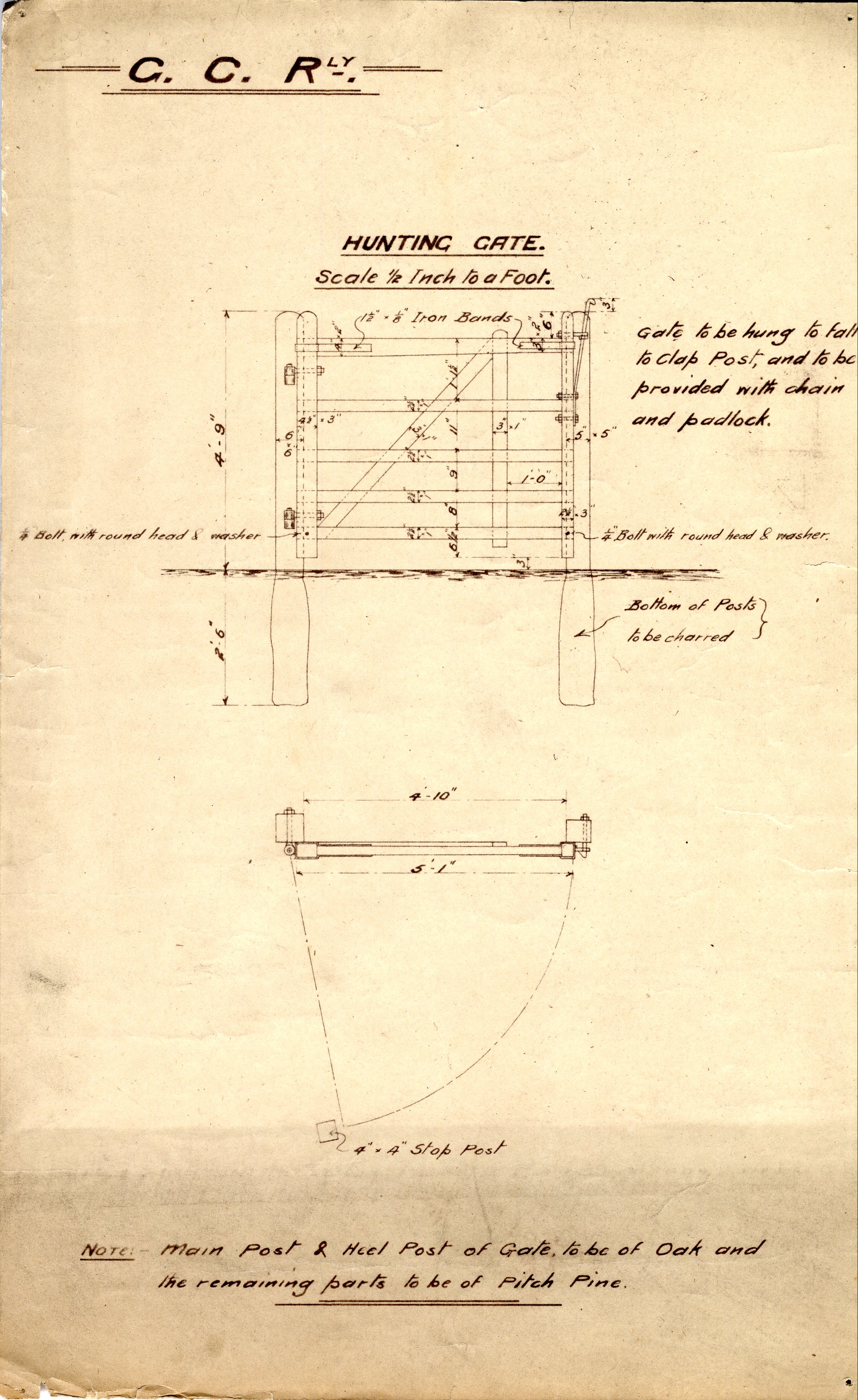
Hunting Gate
Plan
Elevation
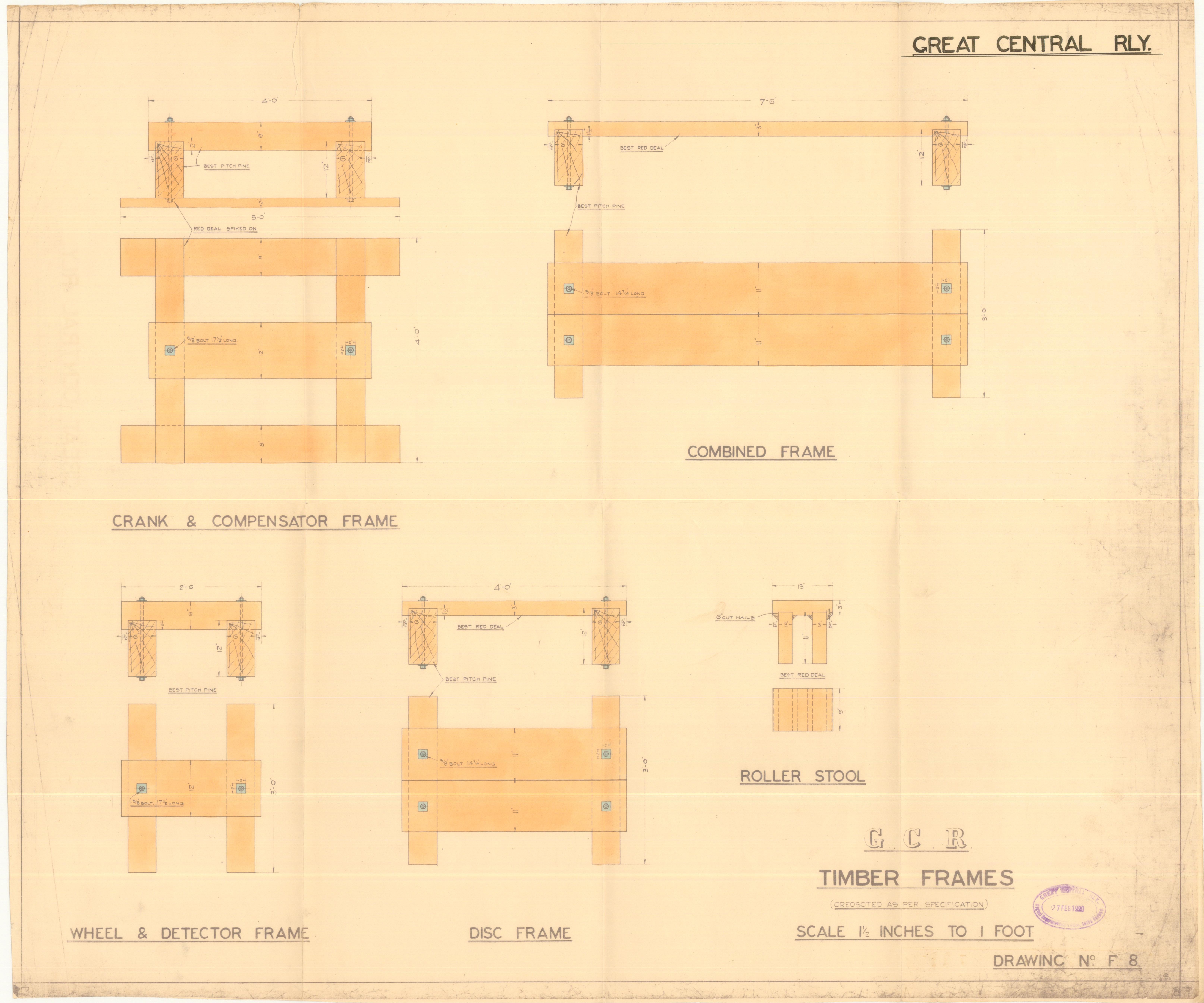
Drawing F8
Timber Frames
Crank & Compensator Frame
Combined Frame
Wheel & Detector Frame
Disc Frame
Roller Stool
Dated 27th February 1920
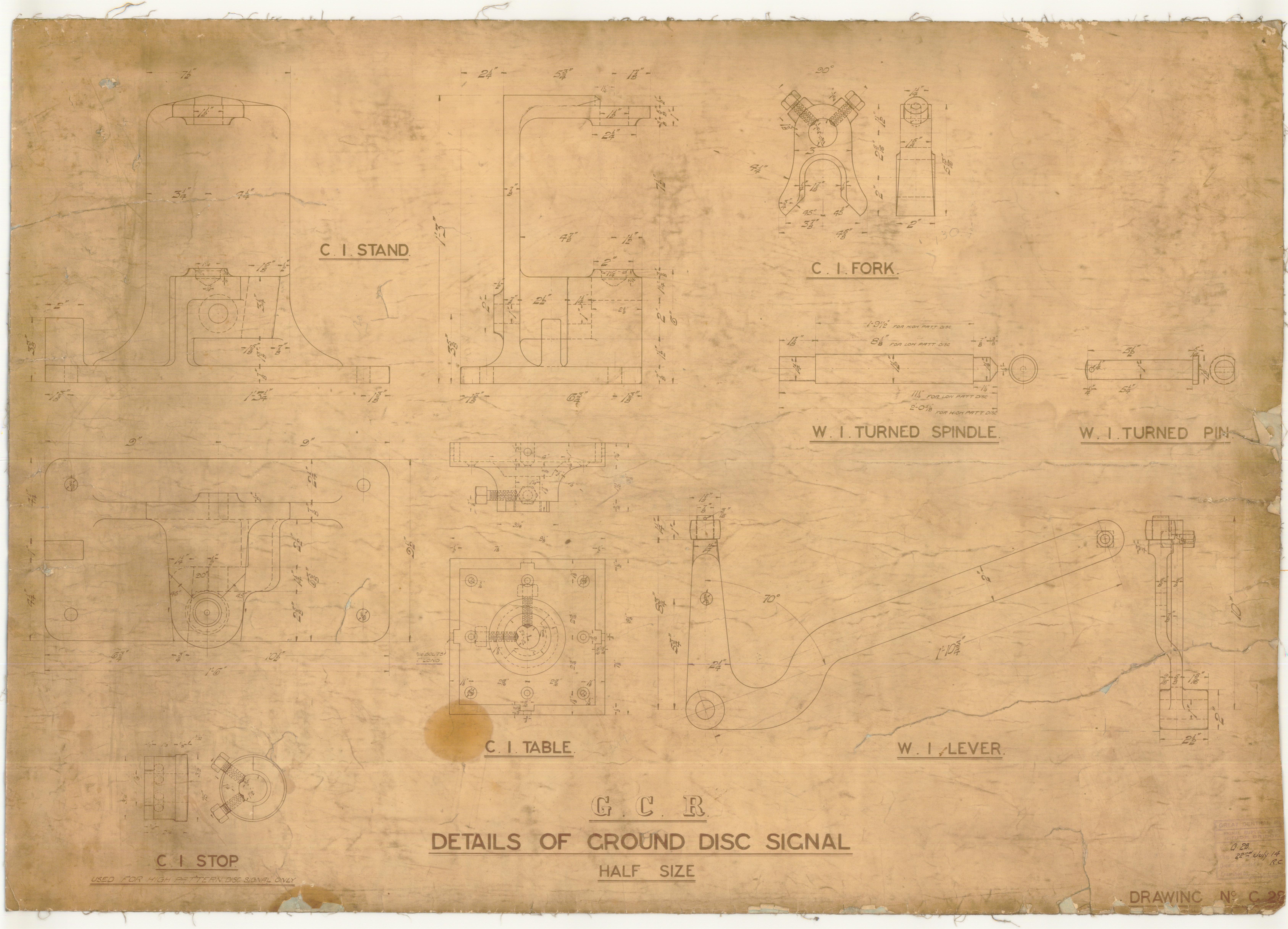
Drawing G28
Details of Ground Disc Signal
C.I. Stand
C.I. Fork
W.I. Turned Spindle
C.I. Stop
C.I. Table
W.I. Lever
Dated 22nd July 1914
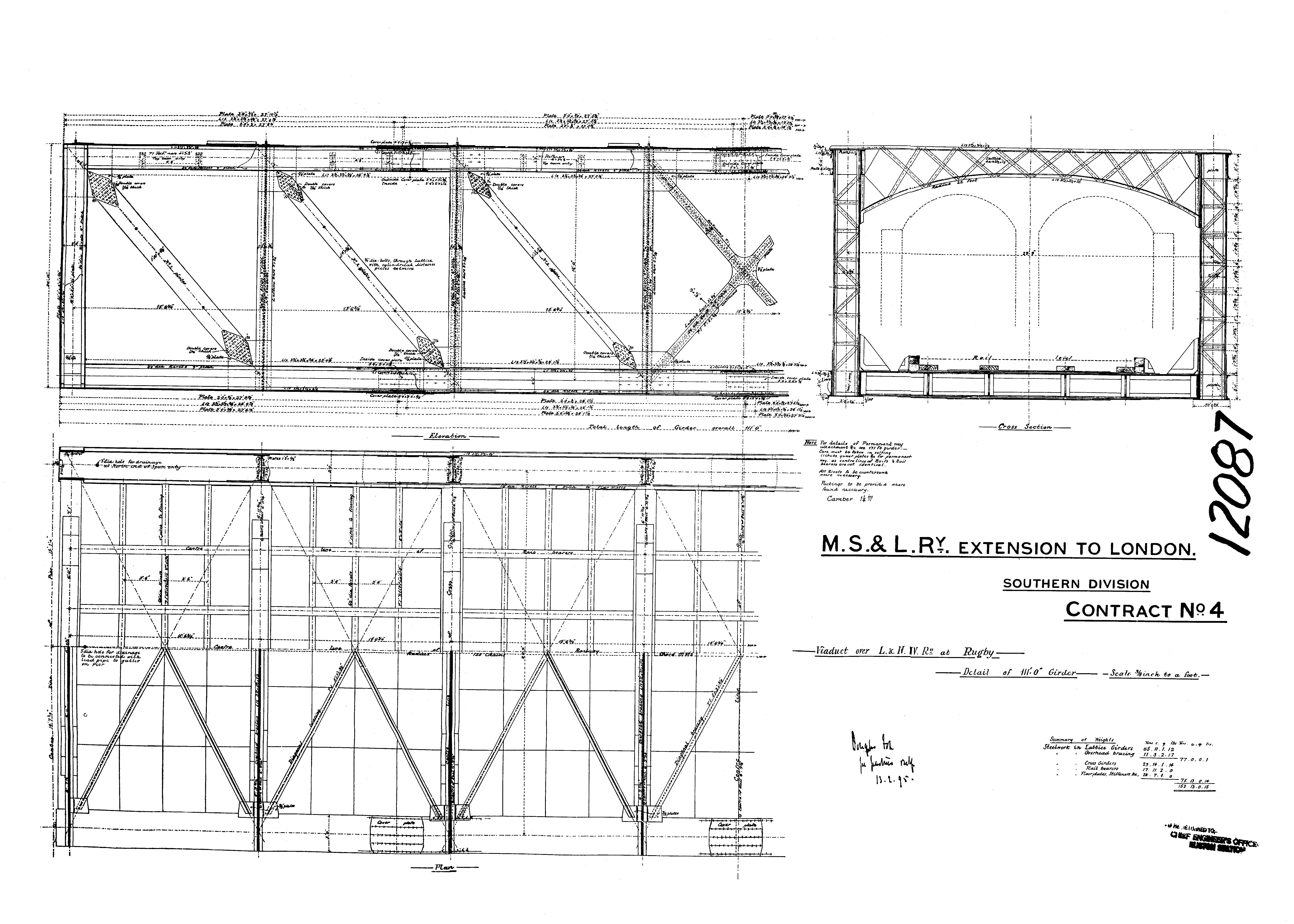
Rugby "Birdcade Bridge" over LNWR
Elevation
Sections
Plan
Drawing courtesy of Mr. Tony West
`
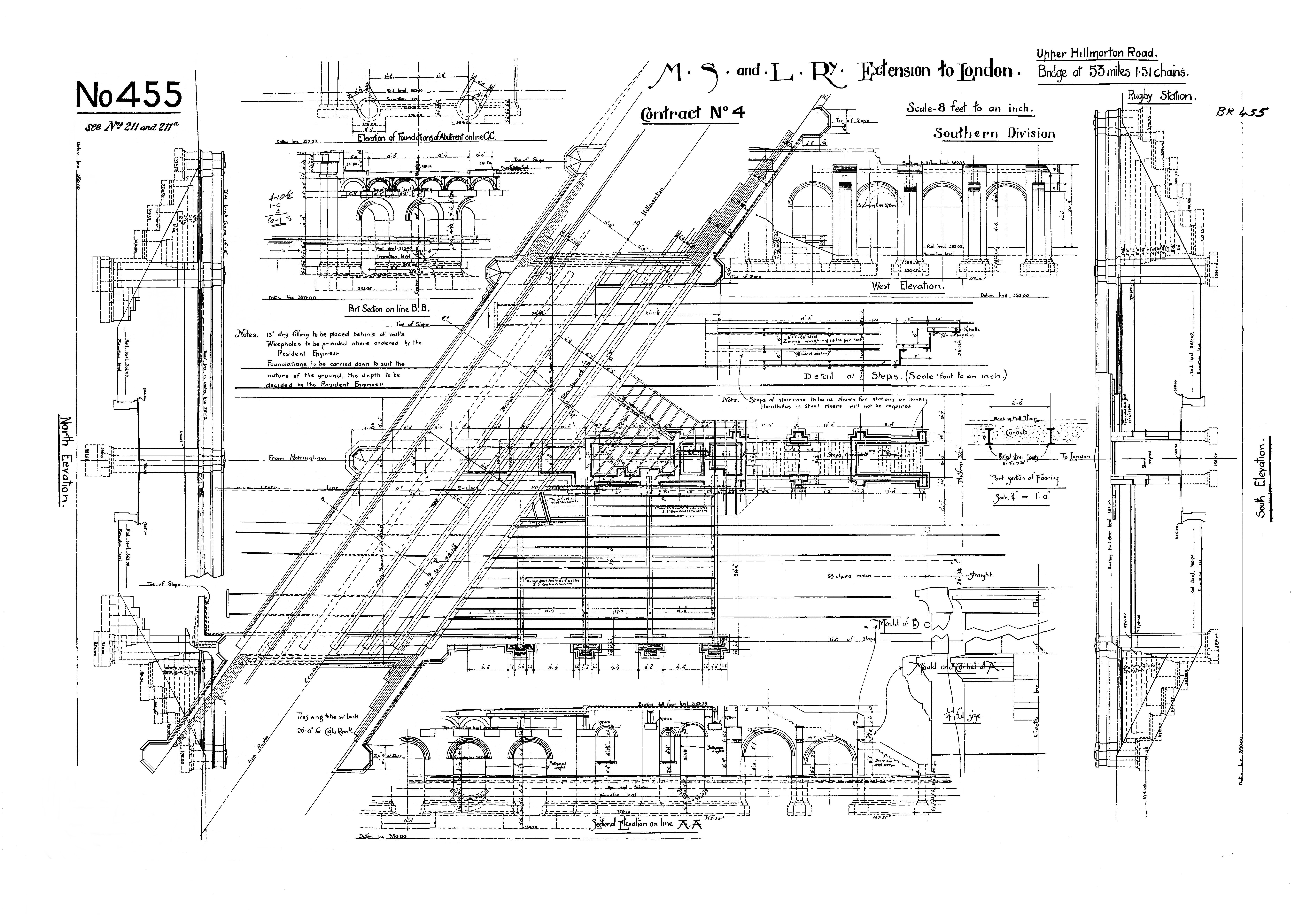
Rugby Station Bridge
Elevation
Sections
Plan
Drawing courtesy of Mr. Tony West
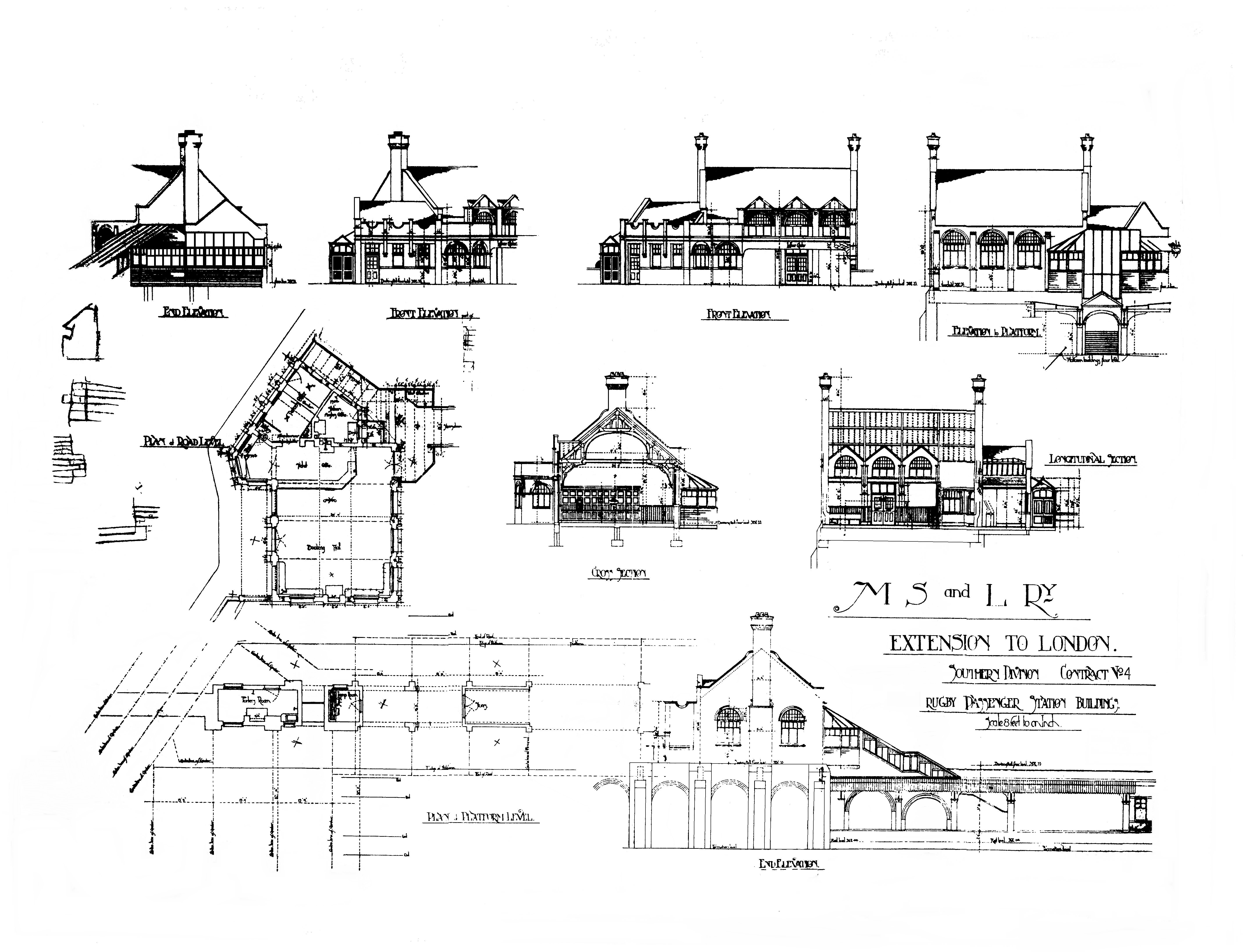
Rugby Station Street Level Buildings
Elevation
Sections
Plan
Drawing courtesy of Mr. Tony West